Table of Contents
Advertisement
Quick Links
TDFM-9000
MULTIBAND P25 AIRBORNE TRANSCEIVER
Operating Instructions
TiL Document No. 11RE441
Rev. G
OCTOBER 2019
Technisonic Industries Limited
240 Traders Boulevard, Mississauga, Ontario L4Z 1W7
Tel: (905) 890-2113 Fax: (905) 890-5338
www.til.ca
Copyright by Technisonic Industries Limited. All rights reserved.
Advertisement
Table of Contents

Subscribe to Our Youtube Channel
Related Manuals for TIL TDFM-9000


Summary of Contents for TIL TDFM-9000
- Page 1 TDFM-9000 MULTIBAND P25 AIRBORNE TRANSCEIVER Operating Instructions TiL Document No. 11RE441 Rev. G OCTOBER 2019 Technisonic Industries Limited 240 Traders Boulevard, Mississauga, Ontario L4Z 1W7 Tel: (905) 890-2113 Fax: (905) 890-5338 www.til.ca Copyright by Technisonic Industries Limited. All rights reserved.
- Page 3 TECHNISONIC INDUSTRIES LIMITED REVISION HISTORY [ 11RE441 ] For the most current revision of this document, please check the Technisonic website: www.til.ca EDITED PAGE DESCRIPTION DATE Front Page Replaced TDFM-9000 Photo with Current Picture. Aug. 13, 2013 Document Now References Correct TIB.
- Page 4 TECHNISONIC INDUSTRIES LIMITED This page is intentionally left blank. TDFM-9000 Operating Instructions TiL 11RE441 Rev. G...
- Page 5 Changes or modifications not expressly approved by Technisonic Industries could void the user’s authority to operate the equipment. WARRANTY INFORMATION The Model TDFM-9000 Transceiver is under warranty for one year from date of purchase. Failed units caused by defective parts or workmanship should be returned to: Technisonic Industries Limited...
- Page 6 Technisonic website www.til.ca for the latest issue of available STCs and letter of authorization for use. WARNING AND DISCLAIMER This manual is designed to provide information about the TDFM-9000. Every effort has been made to make this manual as complete and accurate as possible.
-
Page 7: Table Of Contents
LATITUDE S200-P12 PHONE MODE ................22 WARRANTY ........................24 LIST OF FIGURES FIGURE TITLE PAGE Front Panel Controls – TDFM-9000 Transceiver ............5 Programming Cable: P/N 127499 ................... 13 Encryption Keyloading Cable: P/N 127500 ..............13 LIST OF TABLES TABLE TITLE PAGE TDFM 9000 Series TPL (CTCSS) Codes ................ - Page 8 TECHNISONIC INDUSTRIES LIMITED This page is intentionally left blank. TDFM-9000 Operating Instructions TiL 11RE441 Rev. G...
-
Page 9: Introduction
NOTE: This publication supports radios with Version 2.0.0 or higher software. DESCRIPTION The TDFM-9000 transceiver is an airborne multi-band radio capable of operation in conventional, analog, P25 and P25 phase II digital FM systems, SmartNet/SmartZone trunking systems, and P25 9600 trunking systems. RF modules are available in single, dual, or Tri bands that support VHF, UHF-LO, UHF-HI, and 700-800 MHz bands. - Page 10 Project Number: P9XXXX represents a 5-digit project number that identifies specific options that are contained in each module and describes the full TDFM-9000 configuration. All model variations are capable of supporting both 28 volt and 5 volt AC or DC backlighting. The units are shipped set to operate on 28 volt backlighting.
-
Page 11: Technical Characteristics
12.5 kHz Channel Intermodulation * ** * Measured in digital mode per TIA / EIA IS 102.CAAA under nominal conditions. ** Measured in analog mode per TIA / EIA 603 under nominal conditions. TDFM-9000 Operating Instructions TiL 11RE441 Rev. G... - Page 12 TECHNISONIC INDUSTRIES LIMITED This page is intentionally left blank. TDFM-9000 Operating Instructions TiL 11RE441 Rev. G...
-
Page 13: General
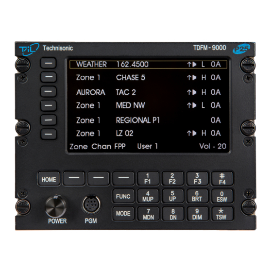
In this configuration, the soft keys on the transceiver provide the audio panel function. It is possible to connect the transceiver such that both methods are used. FRONT PANEL Refer to the diagram below: FIGURE 1: Front Panel Controls – TDFM-9000 Transceiver TDFM-9000 Operating Instructions TiL 11RE441 Rev. G... -
Page 14: Power Switch
For MOD 14 Radios, the bottom side Menu button is used to toggle the Main display from Page 1 to Page 2 when the external transceivers or S200-P12 are enabled. Pressing and holding for one second will toggle the page. TDFM-9000 Operating Instructions TiL 11RE441 Rev. G... -
Page 15: Mode Key
After selecting one of the above the radio will return to normal operating mode. Pressing the ESC soft key will return to normal operating mode without making any changes. Pressing the NEXT soft key will bring up the second function menu. TDFM-9000 Operating Instructions TiL 11RE441 Rev. G... -
Page 16: F1 To F4 Keys
Pressing the ESC soft key or the FUNC key will return the radio to normal operating mode without making any changes. NOTE: Some or all of the above features may be disabled via the Supervisor Menu. Consult TIL or the local Sysop for changes to the enhanced features that are restricted. - Page 17 NOTE: It is possible to use Motorola’s Customer Programming Software (APX CPS™) to alter the default keypad settings of the TDFM-9000 radio. However, if custom key settings are chosen, it will not be possible for Technisonic to help the Pilot or other Radio User through operational difficulties.
-
Page 18: Mup(4) And Mdn(7) Keys (Memory Up And Down Keys)
TECHNISONIC INDUSTRIES LIMITED Modules 1 through 6 of the TDFM-9000 Transceiver are programmable by Motorola CPS™. The following settings may be programmed for each Conventional Channel in a module: TX Frequency Zone TX PL/DPL Code Channel RX Frequency Name RX PL/DPL Code... -
Page 19: Brt(6) And Dim(9) Keys
Switch on the transceiver by pressing the knob. Select the desired band by pressing one of the band select keys on the left of the display. Select the TDFM-9000 on the aircraft audio panel. Press the knob again so that CHAN shows up on the bottom right of the display. Rotate the knob until the desired channel or talk group is selected. -
Page 20: Customer Programming Software (Apx Cps)
A Programming cable “PC-9000” is required to connect the computer to the TDFM-9000. Bands 1 - 6 in the TDFM-9000 are considered an APX portable by the APX CPS™ software. To program a band in the transceiver, it must be selected by pressing the appropriate band select key before running the APX CPS™. -
Page 21: Programming Cable: P/N 127499
TECHNISONIC INDUSTRIES LIMITED FIGURE 2: Programming Cable: “PC-9000” P/N 127499 FIGURE 3: Encryption Keyloading Cable: “KVL-9000” P/N 127500 TDFM-9000 Operating Instructions TiL 11RE441 Rev. G... -
Page 22: Configuration Menu
2.17 CONFIGURATION MENU Some features of the TDFM-9000 transceiver can be configured to the user’s preference. To enter the configuration menu, press the FUNC button, then NEXT, and then select "Configuration" from the 2nd side button. Select the Item by pressing the side button. Rotate the knob to select the desired condition. - Page 23 RF module installed in the radio. Select the desired module then rotate the knob to select colour. A second page is provided for MOD 14 radios with the External transceivers enabled. TDFM-9000 Operating Instructions TiL 11RE441 Rev. G...
-
Page 24: Keyloading Mode
The radio will keep these settings until they are changed again in the configuration menu. If the TDFM-9000 is equipped with hardware encryption, then the Encryption keys will need to be loaded using a Motorola KVL 3000+® or KVL 4000 Keyloader and a KVL-9000 cable, (TiL P/N 127500). -
Page 25: Front Panel Programming (Fpp) Mode
293. The middle soft menu key will allow toggling between 0-9 and A-F. In A-F mode the number keys 1-6 program A- F. Programming a NAC code on an analog channel has no effect. TDFM-9000 Operating Instructions TiL 11RE441 Rev. G... - Page 26 NOTE: The FPP mode will only accept changes if the channel is in a Zone that is FPP enabled in the codeplug. If the channel is in a Zone that is not enabled for FPP, the channel data will be displayed but no changes will be accepted. TDFM-9000 Operating Instructions TiL 11RE441 Rev. G...
-
Page 27: Tdfm 9000 Series Tpl (Ctcss) Codes
TECHNISONIC INDUSTRIES LIMITED The following is a list of supported TDFM-9000 TPL (CTCSS) Codes: PL (Hz) MCODE PL (Hz) MCODE PL (Hz) MCODE PL (Hz) MCODE 67.0 97.4 141.3 206.5 69.3 100.0 146.2 210.7 71.9 103.5 151.4 218.1 74.4 107.2 156.7... -
Page 28: Latitude S200-P12 Satcom Control
During receive, the squelch LED on the top left of the display will illuminate and the caller ID, direction, and distance will be shown on the status line. TDFM-9000 Operating Instructions TiL 11RE441 Rev. G... - Page 29 To scan the selected channels, press the SCAN soft key. The channel name will show as ‘SCANNING.’ Press the STOP soft key to stop. TDFM-9000 Operating Instructions TiL 11RE441 Rev. G...
-
Page 30: Latitude S200-P12 Phone Mode
Phone mode also supports text messages to be sent through the Iridium system. These are not the same as normal phone text messages and can only be sent to the dispatcher. The TDFM-9000 can save and recall up to ten commonly used messages. TDFM-9000 Operating Instructions... - Page 31 ESC soft key. Another message may be waiting in the queue. When there are no more messages, the display returns to the normal SATPhone screen. While in this screen, you can return to PTT mode by pressing the PTT soft key. TDFM-9000 Operating Instructions TiL 11RE441 Rev. G...
-
Page 32: Warranty
Technisonic. This Warranty shall not be transferable or assignable to any other persons, firms, or corporations. For warranty registration, please complete the online Warranty Registration Form found at www.til.ca. TDFM-9000 Operating Instructions TiL 11RE441 Rev. G...
Need help?
Do you have a question about the TDFM-9000 and is the answer not in the manual?
Questions and answers