Table of Contents
Advertisement
Quick Links
TDFM-9000
MULTIBAND P25 AIRBORNE TRANSCEIVER
Installation Instructions
TiL Document No. 11RE442
Rev. D
Issue 1
NOVEMBER 2015
Technisonic Industries Limited
240 Traders Boulevard, Mississauga, Ontario L4Z 1W7
Tel: (905) 890-2113 Fax: (905) 890-5338
www.til.ca
Copyright by Technisonic Industries Limited. All rights reserved.
Advertisement
Table of Contents

Related Manuals for TIL TDFM-9000


Summary of Contents for TIL TDFM-9000
-
Page 1: Installation Instructions
TDFM-9000 MULTIBAND P25 AIRBORNE TRANSCEIVER Installation Instructions TiL Document No. 11RE442 Rev. D Issue 1 NOVEMBER 2015 Technisonic Industries Limited 240 Traders Boulevard, Mississauga, Ontario L4Z 1W7 Tel: (905) 890-2113 Fax: (905) 890-5338 www.til.ca Copyright by Technisonic Industries Limited. All rights reserved. - Page 2 TECHNISONIC INDUSTRIES LIMITED This page is intentionally left blank. TDFM-9000 Installation Instructions TiL 11RE442 Rev. D Issue 1...
- Page 3 May 12, 2014 Added Special Order Band Codes. 2 and 11 Specified “Section 2.17 Configuration Menu” Refers to TDFM-9000 Operating Instructions. Added Antenna & Connector Locations as well as Band Display Orientation. Changed Format for Section Headers. B – 5 Corrected Issue Date.
- Page 4 TECHNISONIC INDUSTRIES LIMITED This page is intentionally left blank. TDFM-9000 Installation Instructions TiL 11RE442 Rev. D Issue 1...
- Page 5 Changes or modifications not expressly approved by Technisonic Industries could void the user’s authority to operate the equipment. This manual is designed to provide information about the TDFM-9000. Every effort has been made to make this manual as complete and accurate as possible.
- Page 6 TECHNISONIC INDUSTRIES LIMITED SUMMARY OF DO-160G ENVIRONMENTAL TESTING Summary of DO-160G Environmental Testing for Technisonic Model TDFM-9000 Transceiver: Conditions Category Temperature and Altitude A2, B1, C4, D1 Temperature Variation Humidity Operational Shock and Crash Safety Vibration S, U Magnetic Effect...
-
Page 7: Table Of Contents
SPEAKER LO AND HI – J6 PINS 8 AND 9..............11 2.21 ANTENNA SELECTION AND INSTALLATION CONSIDERATIONS ......17 2.22 POST INSTALLATION EMI TEST .................. 17 APPENDIX A Support Notes ................... 29 ENVIRONMENTAL QUALIFICATION FORM ..............29 WARRANTY ........................32 TDFM-9000 Installation Instructions TiL 11RE442 Rev. D Issue 1... - Page 8 Wiring Connections for Individual Band Control with a Single Ground Return ....13 Wiring Connections for Combined Band Control with Separate Ground Returns ... 14 Wiring Connections for Combined Band Control with a Single Ground Return ....15 Wiring Connection Notes for the TDFM-9000 Transceiver ..........16 LIST OF TABLES TABLE...
-
Page 9: Introduction
AES and/or DES-OFB encryption with OTAR in any of the available modules. The TDFM-9000 is not normally frequency agile. In order to have the ability to change the frequencies at the front panel, the FPP (front panel programming) option must be ordered for each band. - Page 10 The units are shipped set to operate on 28 Volt back lighting. Equipment can be set to operate on 5V back lighting by using the software based configuration menu. See Section 2.17 Configuration Menu in the TDFM-9000 Operating Instructions available at www.til.ca. Damage will not occur if the incorrect voltage is applied.
-
Page 11: Technical Characteristics
12.5 kHz Channel Intermodulation * ** * Measured in digital mode per TIA / EIA IS 102.CAAA under nominal conditions. ** Measured in analog mode per TIA / EIA 603 under nominal conditions. TDFM-9000 Installation Instructions TiL 11RE442 Rev. D Issue 1... - Page 12 TECHNISONIC INDUSTRIES LIMITED This page is intentionally left blank. TDFM-9000 Installation Instructions TiL 11RE442 Rev. D Issue 1...
-
Page 13: General
INSTALLATION The TDFM-9000 Transceiver is designed to be Dzus mounted and should be installed in conjunction with an IN-9000 installation kit. See Figure 1 for an outline drawing of the unit with dimensions to facilitate the installation. -
Page 14: Outline Drawing
TECHNISONIC INDUSTRIES LIMITED FIGURE 1: Outline Drawing for Model TDFM-9000 TDFM-9000 Installation Instructions TiL 11RE442 Rev. D Issue 1... -
Page 15: Tdfm-9000 Antenna & Connector Locations
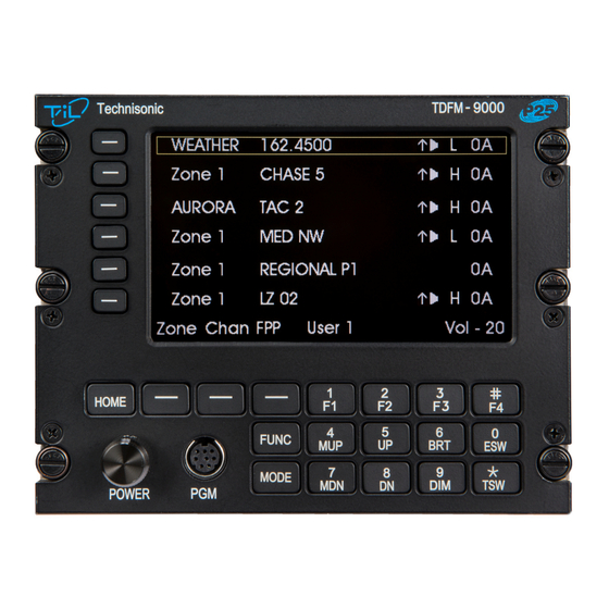
ANT 1 ANT 2 ANT 4 ANT 3 Figure 2: TDFM-9000 Antenna & Connector Locations BANDS Figure 3: TDFM-9000 Band Display Orientation Band display corresponds to the antenna connector numbering and radio ports. Band 1 (top of the display) is connected the ANT 1 and uses the Band 1 connections on the interface connectors. -
Page 16: Installation - Pin Locations And Connections
RX Data Ground Main Power +28 V Down Channel / Band Mic 5 Audio 5 PTT 5 Mic 6 Audio 6 PTT 6 Panel Backlighting TABLE 1: J1 (25 Pin D) Connections TDFM-9000 Installation Instructions TiL 11RE442 Rev. D Issue 1... - Page 17 Audio Ground 5 Audio Ground 6 Audio Ground 3 Audio Ground 4 Audio 1 Audio Ground 1 Ground Audio Combined Ground 1 Audio Combined 1 TABLE 3: J5 (15 Pin HDD) Connections TDFM-9000 Installation Instructions TiL 11RE442 Rev. D Issue 1...
-
Page 18: Installation - Wiring Instructions
There are receive audio, mic audio, and Push To Talk (PTT) lines for each band as well as two sets of lines combining all six bands. The TDFM-9000 can be wired such that band selection can be made on the audio panel. Up to 6 positions need to be available on the audio panel;... -
Page 19: Ptt 1, 2, 3, 5, 6, And 4 - J1 Pins 5, 8, 11, 21, 24, And J6 Pin 3
Select 28 volts or 5 volts via the configuration menu (see Section 2.17 AC/DC of the TDFM-9000 Operating Instructions). No damage will occur if the wrong setting is made. 2.20 SPEAKER LO AND HI – J6 PINS 8 AND 9 Not normally connected in the aircraft. -
Page 20: Wiring Connections For Individual Band Control With Separate Ground Returns
TECHNISONIC INDUSTRIES LIMITED FIGURE 4: Wiring Connections for Individual Band Control with Separate Ground Returns TDFM-9000 Installation Instructions TiL 11RE442 Rev. D Issue 1... -
Page 21: Wiring Connections For Individual Band Control With A Single Ground Return
TECHNISONIC INDUSTRIES LIMITED FIGURE 5: Wiring Connections for Individual Band Control with a Single Ground Return TDFM-9000 Installation Instructions TiL 11RE442 Rev. D Issue 1... -
Page 22: Wiring Connections For Combined Band Control With Separate Ground Returns
TECHNISONIC INDUSTRIES LIMITED FIGURE 6: Wiring Connections for Combined Band Control with Separate Ground Returns TDFM-9000 Installation Instructions TiL 11RE442 Rev. D Issue 1... -
Page 23: Wiring Connections For Combined Band Control With A Single Ground Return
TECHNISONIC INDUSTRIES LIMITED FIGURE 7: Wiring Connections for Combined Band Control with a Single Ground Return TDFM-9000 Installation Instructions TiL 11RE442 Rev. D Issue 1... -
Page 24: Wiring Connection Notes For The Tdfm-9000 Transceiver
CONNECTION TO AN OPTIONAL SRA-6000 SWITCHED RECEIVE ATTENUATOR. OPTIONAL DONGLE USED WHEN A SINGLE AUDIO OUTPUT GROUND RETURN IS REQUIRED. OPTIONAL POWER LINE FILTER. FIGURE 8: Wiring Connection Notes for the TDFM-9000 Transceiver TDFM-9000 Installation Instructions TiL 11RE442 Rev. D Issue 1... -
Page 25: Antenna Selection And Installation Considerations
When single band modules are installed, a single band antenna should be used. If the TDFM-9000 has more than one single band module installed that are on different frequency bands, a single multiband antenna with separate connectors or a multiband antenna with a coupler can be used if the frequencies in use are not multiples of each other. - Page 26 For example, it is permissible for a VFR certified GPS to lose navigation capability while the TDFM-9000 unit is transmitting, providing that it recovers properly and promptly, but it is not permissible for an IFR Approach certified GPS to be affected in the same way.
- Page 27 Determine if the image frequency for the VHF Comm falls within the range of the TDFM- 9000. If so, select a set of frequencies that will cause the TDFM-9000 to be set as close as possible to the image frequency. Any one of the many possible sets will suffice.
- Page 28 Determine if the image frequency for the VOR/ILS Nav falls within the range of the TDFM- 9000. If so, select two sets of frequencies that will cause the TDFM-9000 to be set as close as possible to the image frequency. Choose one set in the localizer frequency range and one in the VOR frequency range.
- Page 29 ILS to be used. Divide the glide slope frequency by 2 and program into the TDFM-9000. Fly the aircraft to intercept the localizer and glide slope (both needles centered) at 26 nm from the runway. Transmit on the TDFM-9000 for 10 seconds and watch for any deflections or flags.
- Page 30 TDFM-9000 PASS FAIL 334.7 (108.1) 167.35 NOTES: Operate the TDFM-9000 transmitter on the following frequency for at least 20 seconds. Observe the Transponder for any spurious replies or loss of reply to test set. FREQUENCIES TRANSPONDER #1 TRANSPONDER #2 TDFM-9000...
- Page 31 TECHNISONIC INDUSTRIES LIMITED Modulate the TDFM-9000 transmitter on the following frequencies for at least 20 seconds. Observe the DME displays. Look for loss of distance information on the display. FREQUENCIES RESULTS DME 1 TDFM-9000 PASS FAIL 978 (108.0) 1020 (112.1)
- Page 32 Frequency #2 Frequency #3 At a safe altitude, engage the autopilot or stability augmentation system. Modulate the TDFM-9000 transmitter on the above frequencies for at least 20 seconds. Observe any effect on the autopilot or stability augmentation system. Observations: Perform a coupled ILS approach to the aircraft's certified limits. Modulate the TDFM-9000 transmitter on the above frequencies for at least 20 seconds.
- Page 33 Glideslope 1 & 2 (UHF Lo, UHF Hi, and 800 MHz) VOR/LOC 1 & 2 (UHF Lo, UHF Hi, and 800 MHz) Compass Directional Gyro Fuel Pressure Oil Temp Amps Bus Voltage TDFM-9000 Installation Instructions TiL 11RE442 Rev. D Issue 1...
- Page 34 TECHNISONIC INDUSTRIES LIMITED Fuel % Torque % Annunciators Digital Clock Oil Pressure DME 1 & 2 (VHF, UHF Lo, and 800 MHz) GPS 1 & 2 (UHF Lo and 800 MHz) TDFM-9000 Installation Instructions TiL 11RE442 Rev. D Issue 1...
- Page 35 TECHNISONIC INDUSTRIES LIMITED STEP SYSTEM PASS FAIL NOTES NOTES: TDFM-9000 Installation Instructions TiL 11RE442 Rev. D Issue 1...
- Page 36 TECHNISONIC INDUSTRIES LIMITED This page is intentionally left blank. TDFM-9000 Installation Instructions TiL 11RE442 Rev. D Issue 1...
-
Page 37: Appendix A Support Notes
240 Traders Blvd., Mississauga, Ontario Canada L4Z 1W7 Tel: 905-890-2113 Fax: 905-890-5338 Tested to: RTCA / DO-160G (December 8, 2010) Date Tested: April 22, 2013 – May 23, 2013 Test Report No: 13RE469 TDFM-9000 Installation Instructions TiL 11RE442 Rev. D Issue 1... - Page 38 Induced Signal Susceptibility 19.0 Radio Frequency Susceptibility 20.0 See NOTE-1 Radio Frequency Emission 21.0 See NOTE-1 Lightning Induced Transient Susceptibility 22.0 Not tested Lightning Direct Effects 23.0 Not tested Icing 24.0 Not tested TDFM-9000 Installation Instructions TiL 11RE442 Rev. D Issue 1...
- Page 39 Indicated test was performed by ULTRATECH LABS. NOTE-2 Testing included subparagraph 16.6.1.3b: Requirement for Equipment with Digital Circuits. NOTE-3 Only applies to units with “MOD 6” marked on the modifications label. TDFM-9000 Installation Instructions TiL 11RE442 Rev. D Issue 1...
-
Page 40: Warranty
Technisonic. This Warranty shall not be transferable or assignable to any other persons, firms, or corporations. For warranty registration, please complete the online Warranty Registration Form found at www.til.ca. TDFM-9000 Installation Instructions TiL 11RE442 Rev. D Issue 1...
Need help?
Do you have a question about the TDFM-9000 and is the answer not in the manual?
Questions and answers