Table of Contents
Advertisement
Quick Links
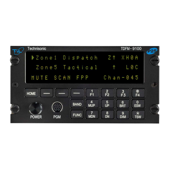
TDFM-9100
MULTIBAND P25 AIRBORNE TRANSCEIVER
Installation Instructions
TiL Document No. 13RE483
Rev. A
NOVEMBER 2014
Technisonic Industries Limited
240 Traders Boulevard, Mississauga, Ontario L4Z 1W7
Tel: (905) 890-2113 Fax: (905) 890-5338
www.til.ca
Copyright by Technisonic Industries Limited. All rights reserved.
Advertisement
Table of Contents

Subscribe to Our Youtube Channel
Related Manuals for TIL TDFM-9100


Summary of Contents for TIL TDFM-9100
-
Page 1: Installation Instructions
TDFM-9100 MULTIBAND P25 AIRBORNE TRANSCEIVER Installation Instructions TiL Document No. 13RE483 Rev. A NOVEMBER 2014 Technisonic Industries Limited 240 Traders Boulevard, Mississauga, Ontario L4Z 1W7 Tel: (905) 890-2113 Fax: (905) 890-5338 www.til.ca Copyright by Technisonic Industries Limited. All rights reserved. - Page 3 REVISION HISTORY [ 13RE483 ] SECTION EDITED DESCRIPTION DATE - PAGE - front Added CI-295-300 antenna 16/10/14...
- Page 5 Changes or modifications not expressly approved by Technisonic Industries could void the user’s authority to operate the equipment. This manual is designed to provide information about the TDFM-9100. Every effort has been made to make this manual as complete and accurate as possible.
- Page 6 SUMMARY OF DO-160G ENVIRONMENTAL TESTING Summary of DO-160G Environmental Testing for Technisonic Model TDFM-9100 Transceiver: Conditions Category Temperature and Altitude A2, B1, C4, D1 Temperature Variation Humidity Operational shock and Crash Safety Vibration S, U Magnetic Effect Power Input Voltage Spike...
-
Page 7: Table Of Contents
Outline Drawing ........................2-2 Wiring connections for separate band control................2-6 Wiring connections for combined band control ................ 2-7 Wiring connections for separate and combined band control ..........2-8 Wiring connection notes for the TDFM-9100 Transceiver ............2-9 TDFM-9100 Installation Instructions TiL 13RE483A... - Page 8 TECHNISONIC INDUSTRIES LIMITED www.til.ca LIST OF TABLES TABLE TITLE PAGE J1 25 Pin D Connections ......................2-3 TDFM-9100 Installation Instructions TiL 13RE483A...
-
Page 9: General Description
These optional additional features include P25 9600 trunking Phase 1 and 2 that may be combined with AES and/or DES-OFB encryption with OTAR in any of the available modules. The TDFM-9100 is not normally frequency agile. In order to have the ability to change the frequencies at the front panel. - Page 10 700 / 800 / UHF LO 700 / 800 / UHF HI Notes: There is only one tray in the TDFM-9100. If only one module is supplied in the tray the second B digit will be a 0 in (TBB).
-
Page 11: Technical Characteristics
25 kHz Channel 12.5 kHz Channel Intermodulation * ** *Measured in digital mode per TIA / EIA IS 102.CAAA under nominal conditions. ** Measured in analog mode per TIA / EIA 603 under nominal conditions. TDFM-9100 Installation Instructions TiL 13RE483A... -
Page 12: General
INSTALLATION The TDFM-9100 Transceiver is designed to be Dzus mounted and should be installed in conjunction with an IN-9100 installation kit. See Figure 2.1 for an outline drawing of the unit with dimensions to facilitate the installation. - Page 13 TECHNISONIC INDUSTRIES LIMITED www.til.ca FIGURE 2.1 Outline Drawing for Model TDFM-9100 TDFM-9100 Installation Instructions TiL 13RE483A...
-
Page 14: Installation - Pin Locations And Connections
PTT Combined TX Data RX Data Ground Main Power +28 VDC Down Channel / Band No Connection No Connection No Connection No Connection No Connection No Connection Panel Backlighting TABLE 2.1 J1 (25 pin D) connections TDFM-9100 Installation Instructions TiL 13RE483A... -
Page 15: Installation - Wiring Instructions
9100 transceiver. There are receive audio, mic audio and PTT lines for each band as well as a set of lines combining both bands. The TDFM-9100 can be wired such that band selection can be made on the audio panel. Two positions need to be available on the audio panel. Otherwise the TDFM-9100 can be wired into one position of the audio panel where band selection and audio monitoring is done on the TDFM-9100 front panel. -
Page 16: Tx Data And Rx Data - J1 Pins 12 And 13
Connect to aircraft panel dimming bus. The transceiver is capable of supporting 28 VAC/DC or 5 VAC/DC backlighting circuits. Select 28 volts or 5 volts via the configuration menu (see section 2.17). No damage will occur if the wrong setting is selected. TDFM-9100 Installation Instructions TiL 13RE483A... - Page 17 TECHNISONIC INDUSTRIES LIMITED www.til.ca FIGURE 2.3 Wiring connections for separate band control. TDFM-9100 Installation Instructions TiL 13RE483A...
- Page 18 TECHNISONIC INDUSTRIES LIMITED www.til.ca FIGURE 2.5 Wiring connections for Combined band control. TDFM-9100 Installation Instructions TiL 13RE483A...
- Page 19 TECHNISONIC INDUSTRIES LIMITED www.til.ca FIGURE 2.6 Wiring connections for Separate and Combined band control. TDFM-9100 Installation Instructions TiL 13RE483A...
- Page 20 TECHNISONIC INDUSTRIES LIMITED www.til.ca FIGURE 2.7 Wiring connection notes for the TDFM-9100 Transceiver TDFM-9100 Installation Instructions TiL 13RE483A...
-
Page 21: Antenna Selection And Installation Considerations
When single band modules are installed, a single band antenna should be used. If the TDFM-9100 has more than one single band module installed that are on different frequency bands, a single multiband antenna with separate connectors or a multiband antenna with a coupler can be used if the frequencies in use are not multiples of each other. -
Page 22: Post Installation Emi Test
2.22 POST INSTALLATION EMI TEST PURPOSE The purpose of this test is to identify any interference that the TDFM-9100 transceiver may cause with existing aircraft systems. TEST CONDITIONS The TDFM-9100 transceiver should be installed and function tested. The antenna VSWR should be checked. - Page 23 For example it is permissible for a VFR certified GPS to lose navigation capability while the TDFM-9100 unit is transmitting, providing that it recovers properly and promptly, but it is not permissible for an IFR Approach certified GPS to be affected in the same way.
- Page 24 Determine if the image frequency for the VHF Comm falls within the range of the TDFM-9100. If so, select a set of frequencies that will cause the TDFM-9100 to be set as close as possible to the image frequency. Any one of the many possible sets will suffice. Record those values in the spaces provided in the following chart.
- Page 25 Determine if the image frequency for the VOR/ILS Nav falls within the range of the TDFM-9100. If so, select two sets of frequencies that will cause the TDFM-9100 to be set as close as possible to the image frequency. Choose one set in the localizer frequency range and one in the VOR frequency range.
- Page 26 With a portable glide slope generator, provide enough signal to firmly activate the indicator needle and hide all flags. Increase the signal level by 3 dB. Modulate the TDFM-9100 transmitter on the following frequencies for at least 20 seconds. Observe the Glide Slope displays. Look for any movement of flags or needles on the navigation display.
- Page 27 TDFM-9100 PASS FAIL 334.7 (108.1) 167.35 NOTES: Operate the TDFM-9100 transmitter on the following frequency for at least 20 seconds. Observe the Transponder for any spurious replies or loss of reply to test set. FREQUENCIES TRANSPONDER #1 TRANSPONDER #2 TDFM-9100...
- Page 28 TECHNISONIC INDUSTRIES LIMITED www.til.ca Modulate the TDFM-9100 transmitter on the following frequencies for at least 20 seconds. Observe the DME displays. Look for loss of distance information on the display. FREQUENCIES RESULTS DME 1 TDFM-9100 PASS FAIL 978 (108.0) 1020 (112.1)
- Page 29 Observations: Perform a coupled ILS approach to the aircraft's certified limits. Modulate the TDFM-9100 transmitter on the above frequencies for at least 20 seconds. Observe any effect on the autopilot. Repeat for second flight director/autopilot if equipped.
- Page 30 (VHF, UHF Lo, and 800 MHz) ADF 1 & 2 Glideslope 1&2 (UHF Lo, UHF Hi, and 800 MHz) VOR/LOC 1&2 (UHF Lo, UHF Hi, and 800 MHz) Compass Directional Gyro Fuel Pressure Oil Temp Amps Bus Voltage TDFM-9100 Installation Instructions TiL 13RE483A 2-19...
- Page 31 TECHNISONIC INDUSTRIES LIMITED www.til.ca Fuel % Torque % Annunciators Digital Clock Oil Pressure DME 1&2 (VHF, UHF Lo, and 800 MHz) GPS 1&2 (UHF Lo and 800 MHz) TDFM-9100 Installation Instructions TiL 13RE483A 2-20...
- Page 32 TECHNISONIC INDUSTRIES LIMITED www.til.ca STEP SYSTEM PASS FAIL NOTES NOTES: TDFM-9100 Installation Instructions TiL 13RE483A 2-21...
-
Page 33: Appendix A Support Notes
+ 85 degrees C High Temperature – Short Time Operating 4.5.3 + 70 degrees C High Temperature – Operating 4.5.4 + 70 degrees C In-Flight Loss of Cooling 4.5.5 not applicable Altitude 4.6.1 50,000 feet TDFM-9100 Installation Instructions TiL 13RE483A 2-22... - Page 34 Other Tests Remarks: All testing was performed at Technisonic Industries unless otherwise indicated. NOTE-1 Indicated test was performed by ULTRATECH LABS. NOTE-2 Testing included subparagraph 16.6.1.3b: Requirement for Equipment with Digital Circuits. TDFM-9100 Installation Instructions TiL 13RE483A 2-23...
- Page 35 TECHNISONIC INDUSTRIES LIMITED www.til.ca NOTES TDFM-9100 Installation Instructions TiL 13RE483A 2-24...
-
Page 36: Warranty
Technisonic. This Warranty shall not be transferable or assignable to any other persons, firms or corporations. For warranty registration please complete the on-line Warranty Registration Form found at www.til.ca.
Need help?
Do you have a question about the TDFM-9100 and is the answer not in the manual?
Questions and answers