Table of Contents
Advertisement
Quick Links
VHF/AM BASE STATIONS
Model TiL-91-DE
LOW POWER SYSTEM NO. 920607 (TBS-150)
15 WATT SYSTEM NO. 910815 (TBS-250)
25 WATT SYSTEM NO. 910825 (TBS-350)
Installation and
Operating Instructions
TiL Document No. 92RE122
Rev. L
AUGUST 2012
Technisonic Industries Limited
240 Traders Boulevard, Mississauga, Ontario L4Z 1W7
Tel: (905) 890-2113 Fax: (905) 890-5338
www.til.ca
Copyright by Technisonic Industries Limited. All rights reserved.
Advertisement
Table of Contents

Subscribe to Our Youtube Channel
Related Manuals for TIL TiL-91-DE


Summary of Contents for TIL TiL-91-DE
-
Page 1: Operating Instructions
LOW POWER SYSTEM NO. 920607 (TBS-150) 15 WATT SYSTEM NO. 910815 (TBS-250) 25 WATT SYSTEM NO. 910825 (TBS-350) Installation and Operating Instructions TiL Document No. 92RE122 Rev. L AUGUST 2012 Technisonic Industries Limited 240 Traders Boulevard, Mississauga, Ontario L4Z 1W7 Tel: (905) 890-2113 Fax: (905) 890-5338 www.til.ca... - Page 3 REVISION HISTORY [ 92RE122 ] SECTION Edited DESCRIPTION DATE - PAGE - Refers to PL revised/replaced in 94RE150 Refers to Sections 5,8 in 94RE150 OCT 09/96 Refers to Sections 5,8 in 94RE150 updated to reflect latest configuration Global New Document Template (new file format) Title page changed, Headers/Footers added Added Revision History and Warranty page Sect 2...
- Page 4 iiii...
- Page 5 WARNING Do not make physical contact with antenna when transmitter is on. CAUTION ! STATIC SENSITIVE ! This unit contains static sensitive devices. Wear a grounded wrist strap and/or conductive gloves when handling printed circuit boards. FCC COMPLIANCE INFORMATION This device complies with Part 15 of the FCC Rules. Operation is subject to the following two conditions: (1) this device may not cause harmful interference and (2) this device must accept any interference received, including interference that may cause undesired operation.
-
Page 7: Table Of Contents
SECTION 1 GENERAL DESCRIPTION INTRODUCTION ....................DESCRIPTION ....................1.2.1 Transceiver - Model Til-91-DE ................1.2.2 Power Supply Modules - Models SPG-007, SPG-015, SPG-025 ........ 1.2.3 RF Amplifier Modules - Models PA-15, PA-25 ............1.2.4 Distribution Boards .................... 1.2.5 Remote Control Boards .................. - Page 8 TITLE PAGE SECTION 3 TRANSCEIVER SETUP AND OPERATING INSTRUCTIONS INTRODUCTION ....................3.1.1 Transceiver Model TiL-91-DE P/N 901006-2 ............3.1.2 Scan Search and Toggle Modes ................3.1.3 Technical Summary ................... OPERATORS SWITCHES, CONTROLS AND INDICATORS ........FRONT PANEL OPERATION ................3.3.1 Keypad "Beeps" ....................
- Page 9 9-Pin Positronics Type Remote Connector Functions ..........REMOTE CONTROL BOARD P/N 923051-1 SETTINGS ........... REMOTE CONTROL BOARD P/N 943180-1 SETTINGS ........... Model Til-91-DE Transceiver Leading Particulars ............ Operators Switches, Controls and Indicators ............Channel/Function Selector Keypad ............... TBS-150, 250, 350 Installation & Operating Instructions...
- Page 10 TECHNISONIC INDUSTRIES LIMITED www.til.ca This page left intentionally blank. TBS-150, 250, 350 Installation & Operating Instructions TiL 92RE122 Rev L viii...
-
Page 11: Introduction
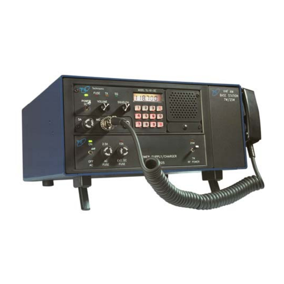
DC power in local and remote operating modes. DESCRIPTION The three base station configurations utilize the keypad entry transceiver (TiL 91-DE) configured for Low Power, 15 Watt or 25 Watt operation. All systems are configured for use of optional Line Interface/Control boards for remote operation. Each base station consists of a Transceiver, Power Supply Module, RF Amplifier Module, Microphone and Control Board (optional). - Page 12 P/N 922062-1 System No. 910825 P/N 901006 Option 1 Item No. TBS-350 NOTE: *Low Power description is found in Table 1.2 under Power Output. FIGURE 1.1 TBS-Series Base Stations TBS-150, 250, 350 Installation & Operating Instructions TiL 92RE122 Rev L...
-
Page 13: Power Supply Modules - Models Spg-007, Spg-015, Spg-025
RF Amplifier Module. Refer to Section 3 for specific details on the Transceiver unique to the systems indicated on the front cover of this document. Transceiver Model Til-91-DE, Part Number 901006-2, is a microprocessor controlled, Low Power VHF/AM transceiver operating over the entire band of 117.975 to 138.000 MHz in 25 kHz steps. -
Page 14: Remote Control Boards
This unit is designed for use with a 50 ohm impedance antenna (not supplied). A 50 ohm RF N type connector (BNC available as an option) is provided on the rear of the unit for interfacing with an antenna. TBS-150, 250, 350 Installation & Operating Instructions TiL 92RE122 Rev L... -
Page 15: Modes Of Operation
VOLUME CONTROL will control the audio level of the external loudspeaker or headphone. 1.3.2 Local/Remote Operation Base Stations which employ the TiL-91-DE transceiver operate in local and remote modes simultaneously. 1. LOCAL OPERATION - In local operation, voice audio, and keying (PTT) functions are routed from the microphone to the transceiver. -
Page 16: Ac And Dc Operation
(1), P/N LCR 12V7.2P, 7.2 amp hour sealed lead acid battery. qty. (1), packing log/ instructions. TECHNICAL SUMMARY A summary of electrical, operational, mechanical and physical characteristics of the Base Station are provided in Tables 1.2 and 3.1. TBS-150, 250, 350 Installation & Operating Instructions TiL 92RE122 Rev L... - Page 17 Height (including feet) ............166 mm (6.5 in) MAX Depth ................274 mm (10.75 in) MAX Weight ................5.5 Kg (12 lbs) MAX * Refer to Section 3 for Transmitter and Receiver Leading Particulars TBS-150, 250, 350 Installation & Operating Instructions TiL 92RE122 Rev L...
- Page 18 TECHNISONIC INDUSTRIES LIMITED www.til.ca This page left intentionally blank TBS-150, 250, 350 Installation & Operating Instructions TiL 92RE122 Rev L...
-
Page 19: Disassembly/Assembly
2.2.2 Remove/Replace Cover Assembly NOTE It is necessary to first remove Microphone Bracket before removing Cover. Remove screws securing Heat Sink to cover last, after removing all other top and bottom screws. TBS-150, 250, 350 Installation & Operating Instructions TiL 92RE122 Rev L... -
Page 20: Remove/Replace Transceiver
(item 11). Connect DC connector (item 10) to rear of transceiver. Connect coaxial connector (item 9) to rear of transceiver. Replace Cover as described in paragraph 2.2.2. TBS-150, 250, 350 Installation & Operating Instructions TiL 92RE122 Rev L... - Page 21 TECHNISONIC INDUSTRIES LIMITED www.til.ca FIGURE 2.1 Base Station Assembly/Disassembly TBS-150, 250, 350 Installation & Operating Instructions TiL 92RE122 Rev L...
-
Page 22: Remove/Replace Power Supply
Remove and retain two bottom screws (item 17) and one rear screw (item 18) securing RF (15W) Power Amplifier (item 20) to chassis (item 4). Note: 25W RF Power Amplifier has four bottom screws (item 17) securing it to the chassis. TBS-150, 250, 350 Installation & Operating Instructions TiL 92RE122 Rev L... -
Page 23: Remove/Replace Distribution Board
Secure control board "piggy back" to the distribution board (item 23) with four screws (item 21). Replace Distribution Board as described in paragraph 2.2.6 and replace Cover as described in paragraph 2.2.2. TBS-150, 250, 350 Installation & Operating Instructions TiL 92RE122 Rev L... -
Page 24: Remote Operation Set Up - Line Interface Boards
11 are connected parallel to pins 8 and 9 on the 9 pin connector. This RJ-11 jack CANNOT be used if the remote control card is set to 4 wire operation as it does not have the necessary connections. TBS-150, 250, 350 Installation & Operating Instructions TiL 92RE122 Rev L... - Page 25 Set J3 for Time out timer OFF (left jumper position) or ON (right jumper position). See Table 2.4 for jumper settings and their functions. See Figure 2.3 for location of jumpers and left/right orientation referred to in the Table 2.4. TBS-150, 250, 350 Installation & Operating Instructions TiL 92RE122 Rev L...
- Page 26 Sets Key Tone Level (Range -40 dBm to 0 dBm). Sets Rx Audio OUT Level (Range -15 dBm to +10 dBm). Sets Timeout Timer (Range 30 to 300 Seconds). Sets Receive Audio Output Balance. TBS-150, 250, 350 Installation & Operating Instructions TiL 92RE122 Rev L...
- Page 27 Keying Tone Attenuator 1950 Tone level Adjustment 2175 Tone Level Adjustment Sets Rx Audio Level Adjustment (Range -15 dBm to +10 dBm). Sets Timeout Timer (Range 30 to 300 Seconds) TBS-150, 250, 350 Installation & Operating Instructions TiL 92RE122 Rev L...
- Page 28 *The SW2 function is now hard wired in the landline current loop keying position and J6 is hard wired for external current loop. CAUTION: Ensure that the J7 jumper is set to the CLK IN position, otherwise damage may occur when transmitting. FIGURE 2.2 Line Interface/Remote Control Board P/N 923051-1 TBS-150, 250, 350 Installation & Operating Instructions TiL 92RE122 Rev L 2-10...
- Page 29 Time out timer (90 sec default) Output Connector NOTE: Bold Italics indicate Factory default configurations. Refer to the maintenance manual (94RE150) for alignment and test. FIGURE 2.3 Line Interface/Remote Control Board P/N 943180-1 TBS-150, 250, 350 Installation & Operating Instructions TiL 92RE122 Rev L 2-11...
-
Page 30: Optional Loudspeaker, Headphone Installation
Section 3 of this document and the appropriate specified operating procedures during transmission. 2.6 STORAGE To store for an extended period, store unit in its original shipping container in a dry place, TBS-150, 250, 350 Installation & Operating Instructions TiL 92RE122 Rev L 2-12... -
Page 31: Operators Switches, Controls And Indicators
12-key keypad. Current operating frequency is displayed on a backlit liquid crystal display (LCD). Option 1 of Model Til-91-DE P/N 901006-2 has an internal DC to DC converter for operation of an RF Power Amplifier in the 15 Watt and 25 Watt Base Stations. - Page 32 TECHNISONIC INDUSTRIES LIMITED www.til.ca FIGURE 3.1 91-DE Base Station Setup TBS-150, 250, 350 Installation & Operating Instructions TiL 92RE122 Rev L...
- Page 33 TECHNISONIC INDUSTRIES LIMITED www.til.ca TABLE 3.1 MODEL TiL-91-DE TRANSCEIVER LEADING PARTICULARS GENERAL: Dimensions & Weight: Width .................. 216 mm (8.5 in) MAX Height (including feet) ............70 mm (2.75 in) MAX Depth ................260 mm (10.25 in) MAX Weight ................
- Page 34 TECHNISONIC INDUSTRIES LIMITED www.til.ca FIGURE 3.2 Base Station Front and Rear Panel Layout TBS-150, 250, 350 Installation & Operating Instructions TiL 92RE122 Rev L...
- Page 35 PRESS TO TALK (PTT) switch determines transceiver operating mode. When the PTT switch is pressed, the transceiver operates in Tx mode. When the PTT switch is released, the transceiver operates in Rx mode. TBS-150, 250, 350 Installation & Operating Instructions TiL 92RE122 Rev L...
- Page 36 CONNECTOR -*EXTERNAL DC Chassis mounted connector provides for Connection to External CONNECTOR DC Supply Source. Mates with DC power cable P/N 863701-1. * Denotes items located on rear panel. TBS-150, 250, 350 Installation & Operating Instructions TiL 92RE122 Rev L...
-
Page 37: Front Panel Operation
FRONT PANEL KEYPAD OPERATION Note: The TiL-91-DE transceiver was available in either 10 or 25 channel versions until July 2012. The 25 channel version can be identified by ‘25’ or ‘1283T’ on the option label on those units. All units manufactured after July 2012 are 25 channel only. -
Page 38: Keypad "Beeps
3.3.3 Transmitter Time-out A 90 second time-out timer is provided to prevent accidental continuous transmission. Press to initiate 90 second Tx time-out protection. Press to disable 90 second Tx time-out protection. TBS-150, 250, 350 Installation & Operating Instructions TiL 92RE122 Rev L... -
Page 39: Selecting A Frequency
After keypad entry of a desired frequency, normal Tx/Rx operation can begin or the frequency can be stored as a channel as described in paragraph 3.3.5 (Storing a Frequency to a Channel). TBS-150, 250, 350 Installation & Operating Instructions TiL 92RE122 Rev L... -
Page 40: Storing A Frequency To A Channel
Channel 1 frequency 119.750 MHz stored in the Channel 01 frequency 119.750 MHz stored in the previous example will be displayed. previous example will be displayed. Example: Example: Press Press TBS-150, 250, 350 Installation & Operating Instructions TiL 92RE122 Rev L 3-10... -
Page 41: Transmit Inhibit
Recall Channel 0 as described in para. 3.3.6 (Recalling a Stored Channel). 117.975 will be displayed. Recall Channel 2 138.000 will be displayed. Press 117.975 will be displayed. Press 138.000 will be displayed. TBS-150, 250, 350 Installation & Operating Instructions TiL 92RE122 Rev L 3-11... -
Page 42: Search Mode
Pressing PTT once exits SCAN mode. Pressing PTT twice is required to Key the Transmitter. Press to enter SCAN mode. Press PTT to Lock on SCANned Frequency or Press to exit SCAN. TBS-150, 250, 350 Installation & Operating Instructions TiL 92RE122 Rev L 3-12... -
Page 43: Fixed Channel Frequency Set Up
Recall Channel "0" frequency. Channel "0" frequency displayed shall be the same frequency entered before Locking the operating configuration (i.e.. different from the frequency entered in step 4). Perform Steps 4 through 6 for each channel. TBS-150, 250, 350 Installation & Operating Instructions TiL 92RE122 Rev L 3-13... - Page 44 TECHNISONIC INDUSTRIES LIMITED www.til.ca FIGURE 3.3 Fixed Channel Jumper Locations TBS-150, 250, 350 Installation & Operating Instructions TiL 92RE122 Rev L 3-14...
-
Page 45: General Operating Instructions
Verify that the POWER ON green LED is ON. (13) Proceed to operate in the transmit mode, paragraph 3.5.3 or operate in the receive mode, paragraph 3.5.4 as required. TBS-150, 250, 350 Installation & Operating Instructions TiL 92RE122 Rev L 3-15... -
Page 46: Transmitter Operation
The transceiver is now operating in the receive mode. Verify that the Tx ON amber LED is OFF. Refer to previous paragraphs for Transceiver Operation and additional operating modes. TBS-150, 250, 350 Installation & Operating Instructions TiL 92RE122 Rev L 3-16... -
Page 47: Receiver Operation
The VOLUME control will now control the audio level applied to the external loudspeaker or headset, as applicable. Refer to previous paragraphs for transceiver specific operating modes. TBS-150, 250, 350 Installation & Operating Instructions TiL 92RE122 Rev L 3-17... -
Page 48: Switching Off
Vdc. The 15 watt and 25 watt units can operate within the range 21.6 Vdc to 30 Vdc. The Low Power units can operate within the range of 11.5 Vdc to 15 Vdc. TBS-150, 250, 350 Installation & Operating Instructions TiL 92RE122 Rev L 3-18... -
Page 49: Warranty
Technisonic. This Warranty shall not be transferable or assignable to any other persons, firms or corporations. For warranty registration please complete the on-line Warranty Registration Form found at www.til.ca.
Need help?
Do you have a question about the TiL-91-DE and is the answer not in the manual?
Questions and answers