
Related Manuals for Bodyworx J1650EA


Summary of Contents for Bodyworx J1650EA
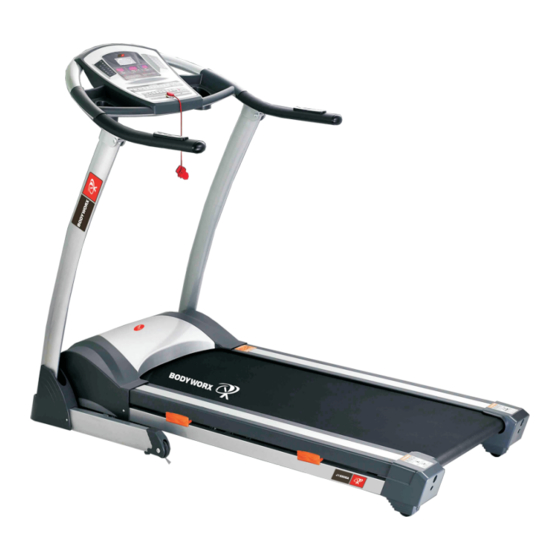
- Page 1 Motorised Treadmill BODY WORX BODY WORX Model No: J1650EA Retain this owner’s manual for future reference Read and follow all instructions in this owner’s manual Version A...
- Page 2 INTRODUCTION Computer Safety Hand bar Handle pulse Motor cover Upright post Side rail Bottom frame Main frame Rear cover Owner’s Manual...
-
Page 3: Key Features
KEY FEATURES Congratulations on choosing this treadmill. You have taken the first step to a healthier and more rewarding lifestyle. This treadmill is especially designed to give you reliable performance and enjoyable workout in the comforts of your home. Please find below the features and benefits of this treadmill. ◇... -
Page 4: Important Safety Precautions
IMPORTANT SAFETY PRECAUTIONS When using an electrical product, basic precautions should always be followed. Read all instructions before using this treadmill. GROUNDING INSTRUCTIONS This product must be grounded! If treadmill should malfunction or breakdown, grounding provides a path of least resistance for electrical current to reduce the risk of electrical shock. The product is equipped with a cord having an equipment-grounding conductor and a grounding plug. -
Page 5: Mechanical Safety
MECHANICAL SAFETY ● Before you start to exercise, make sure the unit functions correctly. To maintain the safety level of the exercise equipment does not use a faulty device. ● Replace defective components immediately and/or keep the equipment out of use until repair. -
Page 6: Assembly Instructions
ASSEMBLY INSTRUCTIONS Step 1: Take the machine from the package, put on the level floor; please keep your hand from the connection between the console and the stand post, the stand post and the bottom frame. Step 2: Follow the arrowhead to put on the stand post (please don’t put your hand on the connection), fix the stand post to the bottom frame with the 4pcs bolt M8*50 for each side. - Page 7 Step 3: Follow the arrowhead to put up the console (please don’t put your hand on the connection), fix the console to the stand post with the 2pcs washerΦ8, and 2pcs bolt M8*20. Please tight all the bolts. Step 4: Follow the arrowhead put the plastic cover on the bottom frame Owner’s Manual...
- Page 8 Step 5: Fix the bottom cover with two bolt (ST4*15) each side, then put the casket on the console. Owner’s Manual...
-
Page 9: Setting Up Your Treadmill
SETTING UP YOUR TREADMILL PLACEMENT IN YOUR HOME To make exercise a desirable daily activity for you, the treadmill should be placed in a comfortable and attractive setting. This treadmill is designed to use minimal floor space and to go nicely in your home. ·... -
Page 10: Getting Started
GETTING STARTED TURN POWER ON The On/Off switch for the treadmill is located next to the power supply cord at the back of the motor cover. Flip this switch to the “ON” position. SAFETY TETHER KEY AND CLIP The safety key is designed to cut the main power to the treadmill should your fall. Therefore, the safety key is designed to bring the treadmill to an immediate stop. -
Page 11: Handling Your Treadmill
HANDLING YOUR TREADMILL FOLDING THE TREADMILL 1. Before folding the body of the treadmill, must cut off the power. 2. Check treadmill’s incline if is the original place 3. Uplift the base deck will parallel to the upright, pedal will pop-up by itself 4. -
Page 12: Operating The Console
OPERATING THE CONSOLE ﹕Window and key-press instruction 1,4 Display windows: A: upper Display window: racetrack and program chart B: left Display window: speed and program data C: right Display window: Pulse and Incline data. D: middle Display window: Time and Distance, Calories When the console showing the data that the LED light will shine. - Page 13 C : “start” key : when press this key, buzzer will sound, Put “start”, The window displays 5---4---3---2---1, then the motor start. D : “stop” key : press this key the motor will stop working. E : Speed +/-, adjust the speed 1 – 16 km/h. F : Incline +/-, adjust the incline’s paragraph 0-15% G : Quick Speed: 2, 4, 6, 8, 10, 12, 14, 16 km/h.
- Page 14 A : It shows the normal mode at first and all the parameters are original When starts to enter into the handle modes. B : When at the normal manual modes, press the “Enter/Reset” key enter into the time countdown modes ,the time displays flashing 30:00, press “+” or “-” can set the time count down which can be designed in the range of the time is :5:00-99:00.
- Page 15 ﹕Program mode 1: The original time is designed to 30 minutes. You can just set time between 5:00 to 99:00.Press “+” ”-“ can adjust the set parameter. 2 : press “start” key, the motor start function according to the program. 3 : Press “stop”...
- Page 16 Press “Mode” key, the “Program” window displays F4, which shows you enter into set weight “70”kgs, press speed “+” ”-“ to adjust the weight (The set weight can be from 20 kgs to 150 kgs) Press “Mode” key, the “Program” window displays F05, which shows you have entered into body fat function;...
- Page 17 I : program speed diagram: speed incline speed incline speed incline speed incline speed incline speed incline 11.0 13.0 13.0 11.0 13.0 11.0 11.0 11.0 11.0 13.0 13.0 13.0 13.0 13.0 13.0 speed incline speed incline speed incline speed incline speed incline speed...
-
Page 18: Maintenance
MAINTENANCE CLEANING Remove dust on the treadmill with vacuum or slightly damp cloth. Fold up the deck and clean the floor with vacuum periodically will help to prolong the treadmill product life. Never use solvents on the deck or running belt. Use of solvents can reduce critical lubrication of the deck and belt. -
Page 19: Running Belt Tensioning Adjustment
RUNNING BELT TENSIONING ADJUSTMENT If when you plant your foot on the belt, you can feel a slipping sensation then the belt has stretched and is slipping across the rollers. All belts will stretch over time. This is a normal and common adjustment on any treadmill. - Page 20 CAUTION! Over tightening of the belt will severely shorten the life of the belt and may cause further damage to other components. NOTE: A well lubricated deck will ensure longevity of your treadmill in addition to providing you with the optimal performance. DANGER! To reduce the risk of electrical shock, always unplug the treadmill from the electrical outlet immediately after use and before cleaning.
-
Page 21: Troubleshooting
TROUBLE SHOOTING Problem Reason may happen Mend methods a No electrify Put plug into socket b Not put in the safety Put in the safety key Treadmill will not start c Circuit signal system Check controller’s port and signal wire turnoff d Power supply not open Put switch on the ‘NO’... - Page 22 EXPLODING DIAGRAM Owner’s Manual...
-
Page 23: Part List
PART LIST NAME SPECIFICATION QUANTITY BASE FRAME MAIN FRAME INCLINE FRAME STAND POST CONNECTION MOTOR ASSEMBLE FRAME CONSOLE FRAME OUTSIDE EXTENSION TUBE INSIDE EXTENSION TUBE PLATE FOR RUNNING DECK INSIDE 6CORNER SCREW M10*65 INSIDE 6CORNER SCREW M10*55 INSIDE 6CORNER SCREW M10*45 INSIDE 6CORNER SCREW M8*55... - Page 24 Cross screw ST4*15 Cross screw ST3*10 Cross screw ST4*15 FLAT WASHER Φ10 FLAT WASHER Φ8 SAWTOOTH WASHER Φ5 CAMBER WASHER Φ8 Locknut Locknut POWDER RING LEFT COVER MIDDLE COVER RIGHT COVER SIDERAIL RAIL LEFT END CAP RIGHT END CAP COMPUTER COVER BIG PCB LED PCB casket (L)
- Page 25 KNOB FOAM FEET WEEK BUCKLE STRING SWITCH SWITCH CONTROL BOARD POWER CABLE FILTER If With CE INDUCTANCE if with CE TRANSFORMER MOTOR INCLINE MOTOR RUNNING DECK FRONT ROLLER REAR ROLLER CYLINDER MOTOR BELT RUNNING BELT MAGNETIC RING WIRING PROTECTOR SENSOR WIRING WIRING WASHER...
-
Page 26: Terms And Conditions
WARRANTY TERMS AND CONDITIONS This warranty is valid only in accordance with the conditions set forth below. Warranty applies only while the followings three conditions are met. ▪ It remains in the possession of the original purchaser and proof of purchase is demonstrated. - Page 27 BODYWORX BODY WORX...
Need help?
Do you have a question about the J1650EA and is the answer not in the manual?
Questions and answers