Table of Contents
Advertisement
Advertisement
Table of Contents

Subscribe to Our Youtube Channel
Related Manuals for Bodyworx J1651EA


Summary of Contents for Bodyworx J1651EA
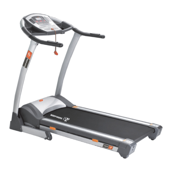
- Page 2 INTRODUCTION Computer Safety Hand bar Handle pulse Motor cover Upright post Side rail Bottom frame Main frame Rear cover Owner’s Manual...
-
Page 3: Key Features
KEY FEATURES Congratulations on choosing this treadmill. You have taken the first step to a healthier and more rewarding lifestyle. This treadmill is especially designed to give you reliable performance and enjoyable workout in the comforts of your home. Please find below the features and benefits of this treadmill. ◇... -
Page 4: Important Safety Precautions
IMPORTANT SAFETY PRECAUTIONS When using an electrical product, basic precautions should always be followed. Read all instructions before using this treadmill. GROUNDING INSTRUCTIONS This product must be grounded! If treadmill should malfunction or breakdown, grounding provides a path of least resistance for electrical current to reduce the risk of electrical shock. The product is equipped with a cord having an equipment-grounding conductor and a grounding lug. -
Page 5: Mechanical Safety
MECHANICAL SAFETY ● Before you start to exercise, make sure the unit functions correctly. To maintain the safety level of the exercise equipment does not use a faulty device. ● Replace defective components immediately and/or keep the equipment out of use until repair. -
Page 6: Assembly Instructions
ASSEMBLY INSTRUCTIONS Step 1 : Take the machine from the package, put on the level floor; please keep your hand from the connection between the console and the stand post, the stand post and the bottom frame. Step 2 : Follow the arrowhead to put on the stand post (please don’t put your hand on the connection),fix the stand post to the bottom frame with the 4pcs bolt M8*50 for each side. - Page 7 Step 3 : Follow the arrowhead to put up the console (please don’t put your hand on the connection), fix the console to the stand post with the 2pcs washerΦ8, and 2pcs bolt M8*20 . Please tight all the bolts. Step 4 : Follow the arrowhead put the plastic cover on the bottom frame Owner’s Manual...
- Page 8 Step 5: Fix the bottom cover with two bolt (ST4*15) each side, then put the casket on the console. Owner’s Manual...
-
Page 9: Setting Up Your Treadmill
SETTING UP YOUR TREADMILL PLACEMENT IN YOUR HOME To make exercise a desirable daily activity for you, the treadmill should be placed in a comfortable and attractive setting. This treadmill is designed to use minimal floor space and to go nicely in your home. ·... -
Page 10: Getting Started
GETTING STARTED TURN POWER ON The On/Off switch for the treadmill is located next to the power supply cord at the back of the motor cover. Flip this switch to the “ON” position. SAFETY TETHER KEY AND CLIP The safety key is designed to cut the main power to the treadmill should your fall. Therefore, the safety key is designed to bring the treadmill to an immediate stop. -
Page 11: Handling Your Treadmill
HANDLING YOUR TREADMILL FOLDING THE TREADMILL 1. Before folding the body of the treadmill, must cut off the power. 2. Check treadmill’s incline if is the original place. 3. Uplift the base deck will parallel to the upright, pedal will pop-up by itself. 4. -
Page 12: Operating The Console
OPERATING THE CONSOLE ﹕Window and key-press instruction 1,4 Display windows: A: upper Display window: racetrack and program chart. B: left Display window: speed and program data. C: right Display window: Pulse and Incline data. D: middle Display window: Time and Distance, Calories When the console showing the data the LED light will shine. - Page 13 C : “start” key : when pressing this key, a buzzer will sound, Put “start”, the window display 5 --- 4 --- 3 --- 2 --- 1, then the motor start. D : “stop” key : press this key the motor will stop working. E : Speed +/-, adjust the speed 1-16 km/h F : Incline +/-,adjust the incline’s paragraph 0-15% G : Quick speed: 2, 4, 6, 8, 10, 12, 14,16km/h.
- Page 14 2 : 3 set functions of the handle functions : Time set, distance set and calorie set. 。 A : It shows the normal mode at first and all the parameters are original when starts to enter into normal modes. B : When at the normal manual modes, press the “mode”...
- Page 15 8: the console sound 3 times during the transition of every part. 9: the designed time slow down to 0, the speed slow down to stop, the buzzer sound 15 times every one second, the middle window transfer to the fixed display time. Press “start” key, speed increase from 1.0km/h to the current speed of the window display.
- Page 16 IX : the display range of numerical value speed incline speed incline speed incline speed incline speed incline speed incline 11.0 13.0 13.0 11.0 13.0 11.0 11.0 11.0 11.0 13.0 13.0 13.0 13.0 13.0 13.0 speed incline speed incline speed incline speed incline...
-
Page 17: Maintenance
I: program speed diagram: original Designed original value Designed range Display range Time (minute : second) 0:00 30:00 5:00-99:00 0:00~99:59 Speed (km/h) 1.0-18.0 Heart rate 00-15 Distance (km) 0.00 1.00 1.00-99.00 0.0-99.99 Calorie (term) 5-9999 0-9999 MAINTENANCE CLEANING Remove dust on the treadmill with vacuum or slightly damp cloth. Fold up the deck and clean the floor with vacuum periodically will help to prolong the treadmill product life. -
Page 18: Lubricating The Deck
IF BELT TOO FAR TO THE LEFT SIDE: 1.Turn the left roller bolt 1/4 turn clockwise (tighten) 2.Turn the right roller bolt 1/4 turn counterclockwise (loosen) IF BELT TOO FAR TO THE RIGHT SIDE: 1.Turn the right roller bolt 1/4 turn clockwise (tighten) 2.Turn the left roller bolt 1/4 turn counterclockwise (loosen) RUNNING BELT TENSIONING ADJUSTMENT If when you plant your foot on the belt, you can feel a slipping sensation then the belt has... - Page 19 TO LUBRICATE THE DECK: Stop running belt so that the seam is located on top and in the center of the deck. Insert nozzle into spray head of lubricant can. Lift running belt. Position nozzle between the belt and the board approximately 200mm (8” ) from the front of the treadmill.
- Page 20 THE ADJUSTMENT OF THE MOTOR BELT Before all the machine leaving the factory, it’s in the best position, but after a period running, the belt may become loose. Adjust the step: Use the wrench adjust electrical engineering stud bolt the agreeable hour hand turns to move.
-
Page 21: Troubleshooting
TROUBLE SHOOTING Problem Reason may happen Mend methods a No electrify Put plug into socket b Not put in the safety key Put in the safety key c Circuit signal system Check controller’s port and signal wire Treadmill will not start turnoff d Power supply not open Put switch on the ‘NO’... - Page 22 EXPLODING DIAGRAM Owner’s Manual...
- Page 23 PART LIST NAME SPECIFICATION QUANTITY BASE FRAME MAIN FRAME INCLINE FRAME STAND POST CONNECTION MOTOR ASSEMBLE FRAME CONSOLE FRAME OUTSIDE EXTENSION TUBE INSIDE EXTENSION TUBE PLATE FOR RUNNING DECK INSIDE 6CORNER SCREW M10*65 INSIDE 6CORNER SCREW M10*55 INSIDE 6CORNER SCREW M10*45 INSIDE 6CORNER SCREW M8*55...
- Page 24 Cross screw ST4*15 Cross screw ST3*10 Cross screw ST4*15 FLAT WASHER Φ10 FLAT WASHER Φ8 SAWTOOTH WASHER Φ5 CAMBER WASHER Φ8 Locknut Locknut POWDER RING LEFT COVER MIDDLE COVER RIGHT COVER SIDERAIL RAIL LEFT END CAP RIGHT END CAP COMPUTER COVER BIG PCB LED PCB casket (L)
- Page 25 KNOB FOAM FEET WEEK BUCKLE STRING SWITCH SWITCH CONTROL BOARD POWER CABLE FILTER If With CE INDUCTANCE if with CE TRANSFORMER MOTOR INCLINE MOTOR RUNNING DECK FRONT ROLLER REAR ROLLER CYLINDER MOTOR BELT RUNNING BELT MAGNETIC RING WIRING PROTECTOR SENSOR WIRING WIRING WASHER...
-
Page 26: Terms And Conditions
WARRANTY TERMS AND CONDITIONS This warranty is valid only in accordance with the conditions set forth below. Warranty applies only while the followings three conditions are met. ▪ It remains in the possession of the original purchaser and proof of purchase is demonstrated.
Need help?
Do you have a question about the J1651EA and is the answer not in the manual?
Questions and answers