Sign In
Upload
Download
Table of Contents
Contents
Add to my manuals
Delete from my manuals
Share
URL of this page:
HTML Link:
Bookmark this page
Add
Manual will be automatically added to "My Manuals"
Print this page
×
Bookmark added
×
Added to my manuals
Manuals
Brands
Advantech Manuals
Desktop
UNO247J1N12502-T
User manual
Advantech UNO247J1N12502-T User Manual
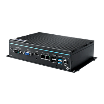
Intel celeron j3455e processor automation computer, with 2x lan, 6x com, 4x usb, 1x hdmi, 1x vga
Hide thumbs
1
2
3
4
5
6
7
8
Table Of Contents
9
10
11
12
13
14
15
16
17
18
19
20
21
22
23
24
25
26
27
28
29
30
31
32
33
34
35
36
37
38
39
40
41
42
43
44
45
46
47
48
49
50
51
52
page
of
52
Go
/
52
Contents
Table of Contents
Bookmarks
Table of Contents
Table of Contents
Chapter 1 Overview
Introduction
Safety Precautions
Accessories
Hardware Specifications
General
Display
Ethernet
Chipset
Functional Specification
Mechanical Specifications
Dimensions
Weight
Power Requirements
System Power
RTC Battery
Environment Specification
Operating Temperature
Relative Humidity
Storage Temperature
Shock During Operation
Safety
Emc
Mounting
Chapter 2 Hardware Functionality
Introduction
Jumpers
Jumper List
Connector
External I/O Connectors
Internal I/O Connectors
Installation
HDD/SSD Installation
RAM Installation
Msata/ Mpcie Card Installation
Installation
Chapter 3 AMI BIOS Setup
Introduction
Entering Setup
Main Setup
Advanced BIOS Features Setup
Chipset
Security
Boot
Save & Exit
Advertisement
Quick Links
Download this manual
User Manual
UNO-247 電腦
Intel® Celeron J3455E processor
Automation Computer, with 2x
LAN, 6x COM, 4x USB, 1x HDMI,
1x VGA
Table of
Contents
Previous
Page
Next
Page
1
2
3
4
5
Advertisement
Table of Contents
Need help?
Do you have a question about the UNO247J1N12502-T and is the answer not in the manual?
Ask a question
Questions and answers
Related Manuals for Advantech UNO247J1N12502-T
Desktop Advantech UNO-2050G User Manual
Lx800 500mhz automation computer with 2 x lan, 2 x rs-232, 2 x isolated rs-232/422/485,16 x isolated di/o (48 pages)
Desktop Advantech UNO-2178A User Manual
Automation computers with intel atom processors, 6 x usb, 8 x com, 2 x mini-pcie (44 pages)
Desktop Advantech UNO-2174A User Manual
Automation computers with intel atom processors, 6 x usb, 8 x com, 2 x mini-pcie (44 pages)
Desktop Advantech UNO-2483G User Manual And Manual
Intel core i7/i3/celeron/atom regular-size automation computer w/ 4/2 x gbe 3/1 x mpcie, hdmi/vga (40 pages)
Desktop Advantech UNO-2271G User Manual
Intel atom pocket-size automation computer with 2 x gbe, 1 x mpcie, hdmi, emmc (26 pages)
Desktop Advantech UNO 2173A/AF User Manual
Intel atom fanless box pc with 1 x lan, 2 x com, mini-pcie (42 pages)
Desktop Advantech UNO-2173A User Manual
Intel atom fanless box pc with 1 x lan, 2 x com, mini-pcie (44 pages)
Desktop Advantech UNO-2272G User Manual
Palm size automation computer (28 pages)
Desktop Advantech UNO-2174G-C54E User Manual
Automation computers with intel core i7 / celeron processors, 4 x gbe, 2 x minipcie, dvi/dp/hdmi (44 pages)
Desktop Advantech UNO-247-J1N1AE User Manual
Intel celeron j3455e processor automation computer, with 2x lan, 6x com, 4x usb, 1x hdmi, 1x vga (52 pages)
Desktop Advantech UNO-247 Series User Manual
Intel celeron j3455e processor automation computer, with 2x lan, 6x com, 4x usb, 1x hdmi, 1x vga (52 pages)
Desktop Advantech UNO-2362G Series User Manual
Automation computer with amd dual core t40e processors,1 x gbe, 1 x mpcie, and hdmi/dp (38 pages)
Desktop Advantech UNO-2372G-J1 Series User Manual
Intel celeron j3455 small form factor modular box platform with 2x gbe, 4x usb, 4x com, 2x mpcie, hdmi, and dp (62 pages)
Desktop Advantech UNO-2372G-J121AE User Manual
Intel celeron j3455 small form factor modular box platform with 2x gbe, 4x usb, 4x com, 2x mpcie, hdmi, and dp (62 pages)
Desktop Advantech UNO-2184G-D45E User Manual
Automation computers with intel core i7 / celeron processors, 4 x gbe, 2 x minipcie, dvi/dp/hdmi (44 pages)
Desktop Advantech UNO-3072LA User Manual
Intel atom embedded automation computer with two pci slot extensions (64 pages)
This manual is also suitable for:
Uno247j1n12504-t
Uno247j1n12506-t
Uno247j1n12503-t
Uno247j1n12505-t
Uno247j1n12501-t
Uno247j1n12406-t
...
Show all
Uno247j1n12405-t
Uno247j1n12404-t
Uno247j1n12403-t
Uno247j1n12402-t
Uno247j1n12401-t
Uno247j1n12306-t
Uno247j1n12305-t
Uno247j1n12304-t
Uno247j1n12303-t
Uno247j1n12302-t
Uno247j1n12301-t
Uno247j1n12206-t
Uno247j1n12205-t
Uno247j1n12204-t
Uno247j1n12203-t
Uno247j1n12202-t
Uno247j1n12201-t
Uno247j1n12106-t
Uno247j1n12105-t
Uno247j1n12104-t
Uno247j1n12103-t
Uno247j1n12101-t
Uno247j1n12102-t
Uno247j1n12006-t
Uno247j1n12005-t
Uno247j1n12004-t
Uno247j1n12003-t
Uno247j1n12002-t
Uno247j1n12001-t
Uno247j1n11903-t
Uno247j1n11902-t
Uno247j1n11901-t
Uno-247-j1n1b
Uno-247-j1n1ae
Uno-247 series
Table of Contents
Print
Rename the bookmark
Delete bookmark?
Delete from my manuals?
Login
Sign In
OR
Sign in with Facebook
Sign in with Google
Upload manual
Upload from disk
Upload from URL


Need help?
Do you have a question about the UNO247J1N12502-T and is the answer not in the manual?
Questions and answers