
Related Manuals for Moxa Technologies EtherDevice EDS-G508E-T


Summary of Contents for Moxa Technologies EtherDevice EDS-G508E-T
- Page 1 EDS-G500E Series Hardware Installation Guide Moxa EtherDevice™ Switch First Edition, July 2013 2013 Moxa Inc. All rights reserved. P/N: 1802005000020...
-
Page 2: Package Checklist
Package Checklist The EDS-G500E is shipped with the following items. If any of these items are missing or damaged, please contact your customer service representative for assistance. • 1 EDS-G508E or EDS-G512E-4GSFP or EDS-G516E-4GSFP Ethernet switch • Hardware installation guide •... -
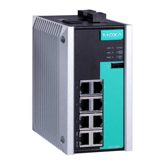
Page 3: Panel Views Of Eds-G500E Series
Panel Views of EDS-G500E Series Front Panel Front Panel 1. 1000BaseT(X) LED indicator 2. 10/100BaseT(X) LED indicator 3. 10/100/1000BaseT(X) ports EDS-G508E: 1 to 8 EDS-G512E-4GSFP: 1 to 8 EDS-G516E-4GSFP: 1 to 12 4. System status LED: • STATE LED indicator •... - Page 4 Top Panel Top Panel 1. Reset button 2. USB console port 3. DIP switches for Turbo Ring, Ring Master, and Ring Coupler 4. Grounding screw 5. 4-pin terminal block for digital input and power input 2 6. 4-pin terminal block for relay output and power input 1 Rear Panel Rear Panel...
-
Page 5: Mounting Dimensions
Mounting Dimensions Unit = mm (inch) - 5 -... -
Page 6: Din-Rail Mounting
DIN-Rail Mounting The metal DIN-rail kit is fixed to the back panel of the EDS-G500E series when you take it out of the box. Mount the EDS-G500E series on corrosion-free mounting rails that meet the EN 60715 standard. Installation STEP 1—Insert the upper lip of the DIN rail into the DIN-rail mounting kit. STEP 2—Press the EDS-G500E series towards the DIN rail until it snaps into place. -
Page 7: Wall Mounting (Optional)
Wall Mounting (Optional) For some applications, you will find it convenient to mount Moxa EDS- G500E series on the wall, as shown in the following illustrations: STEP 1—Remove the aluminum DIN rail attachment plate from the rear panel of the EDS-G500E series, and then attach the wall mount plates with M3 screws, as shown in the figure at the... -
Page 8: Grounding The Moxa Eds-G500E Series
ATTENTION This unit is a built-in type. When the unit is installed in another piece of equipment, the equipment enclosing the unit must comply with fire enclosure regulation IEC 60950/EN60950 (or similar regulation). ATTENTION Safety First! Be sure to disconnect the power cord before installing and/or wiring your Moxa EtherDevice Switch. -
Page 9: Wiring The Redundant Power Inputs
FAULT: The two contacts of the 6-pin terminal block connector are used to detect user-configured events. The two wires attached to the fault contacts form an open circuit when a user-configured event is triggered. If a user-configured event does not occur, the fault circuit remains closed. -
Page 10: Usb Console Connection
USB Console Connection The EDS-G500E series has one USB console port (type B connector), located on the top panel. Use the USB cable (provided in the product package) to connect the EDS-G500E's console port to your PC's USB port and install the USB driver (available in the software CD) on the PC. You may then use a console terminal program, such as Moxa PComm Terminal Emulator, to access the EDS-G500E’s console configuration utility. -
Page 11: 1000Baset Ethernet Port Connection
1000BaseT Ethernet Port Connection 1000BaseT data is transmitted on differential TRD+/- signal pairs over copper wires. MDI/MDI-X Port Pinouts Signal TRD(0)+ TRD(0)- TRD(1)+ TRD(2)+ TRD(2)- TRD(1)- TRD(3)+ TRD(3)- 100/1000BaseSFP (mini-GBIC) Fiber Port The Gigabit Ethernet ports on the EDS-G500E series are 100/1000BaseSFP Fiber ports, which require using the 100M or 1G mini-GBIC fiber transceivers to work properly. -
Page 12: Turbo Ring Dip Switch Settings
paper clip or toothpick, to depress the Reset button. This will cause the STATE LED to blink once a second. After depressing the button for 5 continuous seconds, the STATE LED will start to blink rapidly. This indicates that factory default settings have been loaded and you can release the reset button. -
Page 13: Led Indicators
“Turbo Ring V2” DIP Switch Settings DIP 1 DIP 2 DIP 3 DIP 4 ON: Enables the ON: Enables this ON: Enables the ON: Activates default “Ring EDS as the Ring default “Ring DIP switch 1, 2, Coupling Master. Coupling” port. and 3 to (backup)”... - Page 14 Color Status Description 5. Invalid Ring port connection. Power is being supplied to the main module’s power input PWR1. PWR1 Amber Power is not being supplied to the main module’s power input PWR1. Power is being supplied to the main module’s power input PWR2.
-
Page 15: Specifications
Color Status Description SFP port’s 100 Mbps link is active. 100M Amber Blinking Data is being transmitted at 100 Mbps. (SFP) SFP port’s 100 Mbps link is inactive. SFP port’s 1000 Mbps link is active. 1000M Green Blinking Data is being transmitted at 1000 Mbps. (SFP) SFP port’s 1000 Mbps link is inactive. - Page 16 Dimension 79.2 x 135 x 137 mm (3.1 x 5.3 x 5.4 in) Installation DIN-rail mounting, wall mounting (with optional kit) Environmental Limits Operating -10 to 60°C (14 to 140°F) for standard models Temperature -40 to 75°C (-40 to 167°F) for -T models Storage -40 to 85°C (-40 to 185°F) Temperature...
Need help?
Do you have a question about the EtherDevice EDS-G508E-T and is the answer not in the manual?
Questions and answers
EDS-G512E-4GSFP-T configuration guid line
The configuration guideline for the Moxa EDS-G512E-4GSFP-T includes the following:
- Ports: 8 RJ45 10/100/1000BaseT(X) ports and 4 100/1000BaseSFP fiber ports.
- USB Ports: One USB console port (Type B) and one USB storage port (Type A).
- Buttons and Switches: Reset button and DIP switches for Turbo Ring, Ring Master, and Ring Coupler configuration.
- LED Indicators: Indicators for power (PWR1, PWR2), fault, state, 10/100M, 100/1000M, MSTR/HEAD, CPLR/TAIL, and SFP port status.
- Power Input: Dual redundant DC inputs (12/24/48/-48 VDC), with an input current of 0.4 A @ 24 VDC.
- Alarm and Digital Input: One relay output and one digital input.
- Installation: DIN-rail mounting.
- Protection: Overload current and reverse polarity protection.
- Housing: Metal, IP30-rated.
These features support secure, redundant, and manageable Ethernet switch configuration.
This answer is automatically generated