
Related Manuals for Moxa Technologies EDS-G4008 Series


Summary of Contents for Moxa Technologies EDS-G4008 Series
- Page 1 EDS-G4008 Series Quick Installation Guide Moxa EtherDevice™ Switch Version 1.0, March 2022 Technical Support Contact Information www.moxa.com/support 2022 Moxa Inc. All rights reserved. P/N: 1802040080110 *1802040080110*...
-
Page 2: Package Checklist
Package Checklist The EDS-G4008 Series industrial DIN-rail EtherDevice Switch (EDS) is shipped with the following items. If any of these items are missing or damaged, please contact your customer service representative for assistance. • 1 EDS-G4008 Ethernet switch • Quick installation guide (printed) •... -
Page 3: Mounting Dimensions
Bottom Panel View 1. microSD card slot (currently disabled) 2. Reset button 3. DIP switches for Turbo Ring, Ring Master, and Ring Coupler Mounting Dimensions - 3 -... -
Page 4: Din Rail Mounting
DIN-rail Mounting The DIN-rail mounting kit is fixed to the back panel of the EDS device when you take it out of the box. Mount the EDS device on corrosion- free mounting rails that meet the EN 60715 standard. Installation STEP 1—Insert the upper lip of the DIN rail into the DIN-rail mounting kit. -
Page 5: Wall Mounting (Optional)
Wall Mounting (Optional) For some applications, you will find it convenient to mount the Moxa EDS device on a wall, as shown in the following illustrations: STEP 1—Remove the DIN-rail attachment plate from the rear panel of the EDS device, as illustrated in the diagram on the right. -
Page 6: Wiring Requirements
Wiring Requirements ATTENTION Safety First! External metal parts are hot. Take the necessary precautions if you are required to handle the device. ATTENTION In order to ensure reliable operations, please make sure the operating temperature of the environment does not exceed the specifications. - Page 7 Grounding the Moxa EDS Series Grounding and wire routing help limit the effects of noise due to electromagnetic interference (EMI). Run the ground connection from the ground screw to the grounding surface prior to connecting devices. ATTENTION This product is intended to be mounted to a well-grounded mounting surface such as a metal panel.
-
Page 8: Wiring The Relay Contact
Wiring the Relay Contact The EDS device has one set of relay output. This relay contact uses two contacts of the terminal block on the EDS’s power module. Refer to the section for detailed instructions on how to connect the wires to the terminal block connector, and how to attach the terminal block connector to the terminal block receptor. -
Page 9: Wiring The Digital Inputs
STEP 1: Insert the Positive/Negative DC or Line/Neutral AC wires into the V+/V- or L/N terminals, respectively. STEP 2: To keep the DC or AC wires from pulling loose, use a small flat- blade screwdriver to tighten the wire- clamp screws on the front of the terminal block connector. -
Page 10: Communication Connections
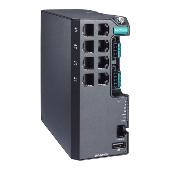
Step 3: Replace the module back on to the EDS device. Step 4: Fasten two screws on to the module. Communication Connections Each EDS-G4008 Series switch has various types of communication ports: • RJ45 console port (RS-232 interface) •... -
Page 11: Reset Button
USB Connection NOTE The USB function is currently reserved and may be required in the future. It should be noted that this port cannot be used for charging any devices. 1000BaseT(X) Ethernet Port Connection 1000BaseT(X) data is transmitted on differential TRD+/- signal pairs over copper wires. -
Page 12: Device Led Indicators
Ring Master, these switches will auto-negotiate to determine which one will be the Ring Master. LED Indicators The front panel of the Moxa EDS-G4008 Series contains several LED indicators. The function of each LED is described in the following table: Device LED Indicators... - Page 13 Color State Description The system has initially failed the boot-up process • System Info. Read Fail or EEPROM information error 1. The relay contact has been triggered 2. The ingress rate limit has been exceeded and the port has entered shut down FAULT mode 3.
-
Page 14: Specifications
Color State Description 1. The switch is set as the Tail of Turbo Chain and the Chain has gone down. Blinking 2. The switch is set as the (4 times/sec) Turbo Chain’s Member/ Head and the corresponding Tail-end Chain port is down. When the switch disables the coupling or tail role of Turbo Chain. - Page 15 Note The EDS-G4008 Series supports modular power supplies. The model names and power parameters are determined by the installed power module. For example: EDS-G4008-T + PWR-100-LV = EDS-G4008-LV-T EDS-G4008-T + PWR-105-HV-I = EDS-G4008-HV- If you install a different power module, refer to the specifications of the corresponding model.
- Page 16 EN 61000-4-2 (ESD) Level 4 EN 61000-4-3 (RS) Level 3 EN 61000-4-4 (EFT) Level 4 EN 61000-4-5 (Surge) Level 4 EN 61000-4-6 (CS) Level 3 EN 61000-4-8 Level 4 Shock IEC 60068-2-27 Free Fall IEC 60068-2-32 Vibration IEC 60068-2-6 Rail Traffic EN 50121-4 (Wayside) Traffic Control...
Need help?
Do you have a question about the EDS-G4008 Series and is the answer not in the manual?
Questions and answers