
Related Manuals for Moxa Technologies EtherDevice EDS-G509-T


Summary of Contents for Moxa Technologies EtherDevice EDS-G509-T
- Page 1 EDS-G509 Hardware Installation Guide Moxa EtherDevice™ Switch Fourth Edition, April 2014 2014 Moxa Inc. All rights reserved. P/N: 1802005090013...
-
Page 2: Package Checklist
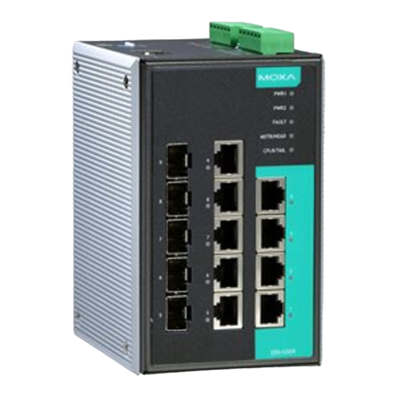
Package Checklist The Moxa EDS-G509 is shipped with the following items. If any of these items is missing or damaged, please contact your customer service representative for assistance. • 1 EDS-G509 EtherDevice Switch • Hardware Installation Guide • CD-ROM with User’s Manual and Windows utility •... - Page 3 Panel Views of EDS-G509 Front Panel: 1. 1 to 4: 10/100/1000 BaseT(X) port 2. 5 to 9: 10/100/1000 BaseT(X) or 100/1000Base SFP slot combo ports 3. PWR1: LED for power input 1 4. PWR2: LED for power input 2 5. FAULT: LED indicator 6.
-
Page 4: Din-Rail Mounting
DIN-Rail Mounting The aluminum DIN-Rail attachment plate should already be fixed to the back panel of the EDS-G509 when you take it out of the box. If you need to reattach the DIN-Rail attachment plate to the EDS-G509, make sure the stiff metal spring is situated towards the top, as shown in the following figures. -
Page 5: Wiring Requirements
STEP 3—Once the screws are fixed to the wall, insert the four screw heads through the wide parts of the keyhole-shaped apertures, and then slide the EDS-G509 downwards, as indicated in the figure at the right. Tighten the four screws for more stability. -
Page 6: Wiring The Relay Contact
Please read and follow these guidelines: • Use separate paths to route wiring for power and devices. If power wiring and device wiring paths must cross, make sure the wires are perpendicular at the intersection point. NOTE: Do not run signal or communications wiring and power wiring through the same wire conduit. -
Page 7: Wiring The Redundant Power Inputs
Wiring the Redundant Power Inputs The EDS-G509 has two sets of power inputs—power input 1 and power input 2. The top two contacts and the bottom two contacts of the 6-pin terminal block connector on the EDS-G509’s top panel are used for the two digital inputs. - Page 8 RJ45 (10-pin) Console Port Pinouts Description RJ45 (10-pin) to DB9 (F) Cable Wiring 10/100/1000BaseT(X) Ethernet Port Connection The 10/100/1000BaseT(X) ports located on Moxa EtherDevice Switch’s front panel are used to connect to Ethernet-enabled devices. Most users will choose to configure these ports for Auto MDI/MDI-X mode, in which case the port’s pinouts are adjusted automatically depending on the type of Ethernet cable used (straight-through or cross-over), and the type of device (NIC-type or HUB/Switch-type) connected to the port.
- Page 9 1000BaseT RJ45 Pinouts MDI-X BI_DA+ BI_DB+ BI_DA- BI_DB- BI_DB+ BI_DA+ BI_DC+ BI_DD+ BI_DC- BI_DD- BI_DB- BI_DA- BI_DD+ BI_DC+ BI_DD- BI_DC- RJ45 (8-pin) to RJ45 (8-pin) Straight-Through Cable Wiring RJ45 (8-pin) to RJ45 (8-pin) Cross-Over Cable Wiring 100 BaseFX or 1000BaseSFP Fiber Port The Gigabit Ethernet ports on the EDS-G509 series are SFP slots, which require 100BaseFX SFP or Gigabit mini-GBIC fiber transceivers to work properly.
-
Page 10: Turbo Ring Dip Switch Settings
Multi mode: 100BaseFX 0 to 5 km, 1300 nm (50/125μm, 800MHz*km) 0 to 4 m, 1300 nm (62.5/125μm, 500MHz*km) Single mode: 100BaseFX 0 to 40 km, 1310 nm (9/125μm, 3.5 PS/(nm*km)) The concept behind the LC port and cable is quite straightforward. Suppose you are connecting devices I and II. - Page 11 EDS-G509 Series DIP Switches The default setting for each DIP Switch is OFF. The following table explains the effect of setting the DIP Switch to the ON position. “Turbo Ring” DIP Switch Settings DIP 1 DIP 2 DIP 3 DIP 4 ON: Enables this ON: Enables the ON: Activates...
-
Page 12: Led Indicators
LED Indicators The front panel of the Moxa EDS-G509 contains several LED indicators. The function of each LED is described in the following table: Color State Description Power is being supplied to power input P1. PWR1 AMBER Power is not being supplied to power input P1. -
Page 13: Specifications
Specifications Technology Standards IEEE802.3, 802.3u, 802.3x, 802.1D, 802.1w, 802.1Q, 802.1p, 802.1X, 802.3ad, 802.3z Protocols IGMPv1/v2, GMRP, GVRP, SNMPv1/v2c/v3, DHCP Server/Client, DHCP Option 66/67/82, BootP, TFTP, SNTP, SMTP, RARP, RMON, HTTP, HTTPS, Telnet, SSH, Syslog, Modbus/TCP, SNMP Inform, LLDP, IEEE 1588 PTP, IPv6 MIB-II, Ethernet-like MIB, P-BRIDGE MIB, Q-BRIDGE MIB, Bridge MIB, RSTP MIB, RMON MIB Group 1,2,3,9... - Page 14 Fast Ethernet SFP-M SFP-S SFP-L Wavelength 1300 nm 1310 nm 1550 nm Max. Tx -18 dBm 0 dBm 0 dBm Min. Tx -8 dBm -5 dBm -5 dBm Rx Sensitivity -34 dBm -34 dBm -34 dBm Link Budget 26 dB 29 dB 29 dB Typical Distance...
- Page 15 Technical Support Contact Information www.moxa.com/support Moxa Americas: Moxa China (Shanghai office): Toll-free: 1-888-669-2872 Toll-free: 800-820-5036 Tel: 1-714-528-6777 Tel: +86-21-5258-9955 Fax: 1-714-528-6778 Fax: +86-21-5258-5505 Moxa Europe: Moxa Asia-Pacific: Tel: +49-89-3 70 03 99-0 Tel: +886-2-8919-1230 Fax: +49-89-3 70 03 99-99 Fax: +886-2-8919-1231 - 15 -...
Need help?
Do you have a question about the EtherDevice EDS-G509-T and is the answer not in the manual?
Questions and answers