Table of Contents
Advertisement
Quick Links
Quick Start Guide
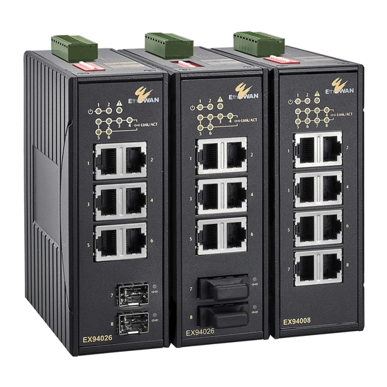
This quick start guide describes how to install and use the
Hardened Ethernet Switch. This is the Switch of choice for
harsh environments constrained by space.
<Note> The contents of Quick Start Guide shall prevail over
the contents of User's Manual in case of discrepancy between
the contents of Quick Start Guide and User's Manual.
Physical Description
The Terminal Assignment
DC Terminal Block Power Inputs: There are two pairs of
power inputs can be used to power up this device.
Redundant power supplies function is supported. You
need to have two power inputs connected to run the
device, but the FAULT LED indicator will light up to
Hardened Ethernet Switch
1
Advertisement
Table of Contents

Related Manuals for EtherWAN EX94000


Summary of Contents for EtherWAN EX94000
-
Page 1: Quick Start Guide
Hardened Ethernet Switch Quick Start Guide This quick start guide describes how to install and use the Hardened Ethernet Switch. This is the Switch of choice for harsh environments constrained by space. <Note> The contents of Quick Start Guide shall prevail over the contents of User’s Manual in case of discrepancy between the contents of Quick Start Guide and User’s Manual. - Page 2 Hardened Ethernet Switch remind that the power redundant system functions abnormal in case either PWR1 or PWR2 is dead. This device, however, continues working normally even fault LED indicator lights up. DC Jack Power input: 12VDC. The 10/100Base-TX and 100Base-FX/BX Connectors 1.
- Page 3 Hardened Ethernet Switch The Port Status LEDs...
- Page 4 Hardened Ethernet Switch State Indication POWER Switch is properly connected to power and Steady PWR1 turned on. PWR2 Switch is not connected to power and is turned (Green) off. FAULT Power redundant system failure occurred. Steady Port failure occurred (when port fault alarm dip switch is enabled).
-
Page 5: Functional Description
Hardened Ethernet Switch Functional Description Meets EN61000-6-2 & EN61000-6-3 EMC Generic Standard Immunity for industrial environment. Supports 802.3/802.3u/802.3x. Auto-negotiation: 10/100Mbps, full/half-duplex; Auto MDI/MDIX. 100Base-FX: Multi mode SC or ST type, Single mode SC or ST type. 100Base-BX: WDM Single mode SC type. - Page 6 Hardened Ethernet Switch Supports DIN-Rail or Panel Mounting installation. For use in Pollution Degree 2 Environment. This equipment is suitable for use in hazardous locations (applicable to versions with terminal block power option). Field Wiring Terminal Markings: Use Copper Conductors Only, 60/75℃, wire range 12-24 AWG, torque value 7 lb-in.
-
Page 7: Preface
Hardened Ethernet Switch Preface A member of the growing family of rugged switches, this switch addresses a need for a smaller switch. This switch provides an affordable solution for rugged and outdoor environment, transportation road-side cabinet, industrial floor shop, multitenant dwellings or Fiber To The Home (FTTH) applications. -
Page 8: Table Of Contents
Hardened Ethernet Switch Table of Contents UICK TART UIDE HYSICAL ESCRIPTION The Terminal Assignment The 10/100Base-TX and 100Base-FX/BX Connectors The Port Status LEDs SSEMBLY TARTUP ISMANTLING UNCTIONAL ESCRIPTION REFACE ABLE OF ONTENTS RODUCT VERVIEW ARDENED THERNET WITCH ACKAGE ONTENTS RODUCT IGHLIGHTS Basic Features RONT... -
Page 9: Product Overview
Hardened Ethernet Switch Product Overview Hardened Ethernet Switch... - Page 10 Hardened Ethernet Switch Package Contents When you unpack the product package, you shall find the items listed below. Please inspect the contents, and report any apparent damage or missing items immediately to your authorized reseller. This Switch User’s Manual ...
-
Page 11: Basic Features
Hardened Ethernet Switch Product Highlights Basic Features Meets EN61000-6-2 & EN61000-6-3 EMC Generic Standard Immunity for industrial environment. Supports 802.3/802.3u/802.3x. Auto-negotiation: 10/100Mbps, full/half-duplex; Auto MDI/MDIX. 100Base-FX: Multi mode SC or ST type, Single mode SC or ST type. 100Base-BX: WDM Single mode SC type. - Page 12 Hardened Ethernet Switch This equipment is suitable for use in Class I, Division 2, Groups A, B, C and D or non-hazardous locations only. WARNING – EXPLOSION HAZARD – Do not disconnect equipment unless power has been removed area known non-hazardous.
-
Page 13: Status Leds
Hardened Ethernet Switch Front Panel Display Status LEDs... - Page 14 Hardened Ethernet Switch State Indication POWER Switch is properly connected to power and Steady PWR1 turned on. PWR2 Switch is not connected to power and is turned (Green) off. FAULT Power redundant system failure occurred. Steady Port failure occurred (when port fault alarm ...
-
Page 15: Installation
Hardened Ethernet Switch Installation This chapter gives step-by-step instructions about how to install the switch: Selecting a Site for the Switch As with any electric device, you should place the switch where it will not be subjected to extreme temperatures, humidity, or electromagnetic interference. - Page 16 Hardened Ethernet Switch...
- Page 17 Hardened Ethernet Switch DIN Rail Mounting Fix the DIN rail attachment plate to the back panel of the switch. Installation: Place the switch on the DIN rail from above using the slot. Push the front of the switch toward the mounting surface until it audibly snaps into place.
- Page 18 Hardened Ethernet Switch...
-
Page 19: Redundant Dc Terminal Block Power Inputs
Hardened Ethernet Switch Connecting to Power Redundant DC Terminal Block Power Inputs or 12VDC DC Jack: Redundant DC Terminal Block Power Inputs There are two pairs of power inputs can be used to power up this device. You need to have two power inputs connected to run the device, but the FAULT LED indicator will light up to remind that the power redundant system functions abnormal in case either PWR1 or PWR2 is dead. -
Page 20: 12Vdc Dc Jack
Hardened Ethernet Switch 12VDC DC Jack Step 1: Connect the supplied AC to DC power adapter to the receptacle on the topside of the switch. Step 2: Connect the power cord to the AC to DC power adapter and attach the plug into a standard AC outlet with the appropriate AC voltage. - Page 21 Hardened Ethernet Switch...
-
Page 22: Alarms For Power And Port Failure
Hardened Ethernet Switch Alarms for Power and Port Failure Step 1: There are two pins on the terminal block are used for power failure detection. It provides the normally closed output when the power source is active. Use this as a dry contact application to send a signal for power failure detection. -
Page 23: Connecting To Your
Hardened Ethernet Switch Connecting to Your Network Cable Type & Length It is necessary to follow the cable specifications below when connecting the switch to your network. Use appropriate cables that meet your speed and cabling requirements. Cable Specifications Speed Connector Port Speed Cable... -
Page 24: Cabling
Hardened Ethernet Switch Cabling Step 1: First, ensure the power of the switch and end devices are turned off. Always ensure that the power is off before any installation. <Note> Step 2: Prepare cable with corresponding connectors for each type of port in use. -
Page 25: Switch
Hardened Ethernet Switch Specifications Hardened Ethernet 10/100Base-TX auto-negotiating ports with RJ-45 connectors, 100Base-FX/BX fiber ports Switch Applicable IEEE 802.3 10Base-T IEEE 802.3u 100Base-TX/FX Standards Store-and-Forward Switching Method Forwarding Rate 10Base-T: 10 / 20Mbps half / full-duplex 100Base-TX: 100 / 200Mbps half / full-duplex 100Base-FX/BX: 200Mbps full-duplex 14,880pps for 10Mbps... - Page 26 Hardened Ethernet Switch EN61000-6-2: EN61000-4-2 (ESD Standards) EN61000-4-3 (Radiated RFI Standards) EN61000-4-4 (Burst Standards) EN61000-4-5 (Surge Standards) EN61000-4-6 (Induced RFI Standards) EN61000-4-8 (Magnetic Field Standards) Environmental Test Compliance IEC60068-2-6 Fc (Vibration Resistance) IEC60068-2-27 Ea (Shock) IEC60068-2-32 Ed (Free Fall)
- Page 27 Hardened Ethernet Switch Appendix A – Connector Pinouts Pin arrangement of RJ-45 connectors: RJ-45 Connector and Cable Pins The following table lists the pinout of 10/100Base-TX ports. Regular Ports Uplink port Output Transmit Data + Input Receive Data + Output Transmit Data - Input Receive Data - Input Receive Data + Output Transmit Data +...
Need help?
Do you have a question about the EX94000 and is the answer not in the manual?
Questions and answers