Advertisement
Quick Links
Quick Start Guide
This quick start guide describes how to install and use the
hardened
Ethernet
temperature extremes of -10°C to +60°C, this is the switch of
choice for harsh environments constrained by space.
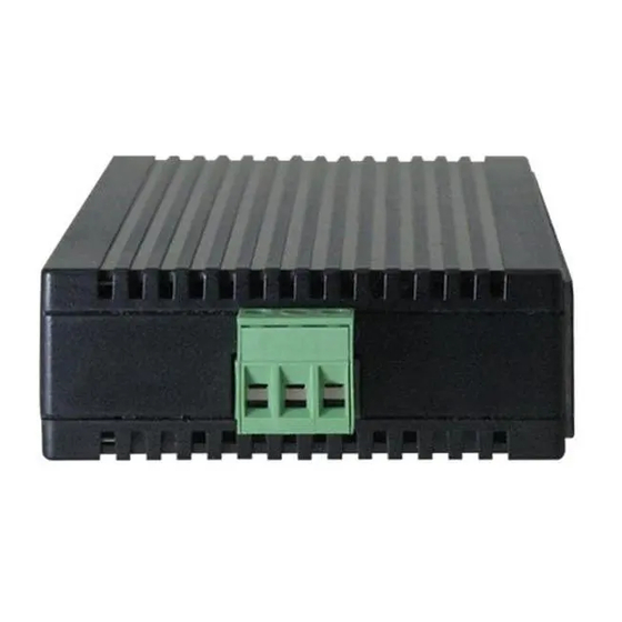
Physical Description
The Terminal Block and Power input
The Terminal Block
PWR
GND
The 10/100Base-TX and 100Base-FX Connectors
1. The 10/100Base-TX Connections
The following lists the pinouts of 10/100Base-TX ports.
Industrial Ethernet Switch
Switch.
Power Input
Power Ground
Earth Ground
1
Capable
of
operating
at
Advertisement

Related Manuals for EtherWAN EX42011


Summary of Contents for EtherWAN EX42011
-
Page 1: Quick Start Guide
Industrial Ethernet Switch Quick Start Guide This quick start guide describes how to install and use the hardened Ethernet Switch. Capable operating temperature extremes of -10°C to +60°C, this is the switch of choice for harsh environments constrained by space. Physical Description The Terminal Block and Power input The Terminal Block... - Page 2 Industrial Ethernet Switch Regular Ports Uplink port Output Transmit Data + Input Receive Data + Output Transmit Data - Input Receive Data - Input Receive Data + Output Transmit Data + Input Receive Data - Output Transmit Data - 2. The 100Base-FX Connections The fiber port pinouts: The Tx (transmit) port of device I is connected to the Rx (receive) port of device II, and the Rx (receive) port of device I to the Tx (transmit) port of device II.
- Page 3 Industrial Ethernet Switch State Indication 10/100TX or 100FX A valid network connection established. Steady LINK stands for LINK. LINK/ACT Transmitting or receiving data. Flashing ACT stands for ACTIVITY. Steady The port is transferring at 100Mbps. The port is transferring at 10Mbps If this LED is dark.
- Page 4 Industrial Ethernet Switch Assembly, Startup, and Dismantling Assembly: Place the switch on the DIN rail from above using the slot. Push the front of the switch toward the mounting surface until it audibly snaps into place. Startup: Connect the supply voltage to start up the switch via the terminal block.
- Page 5 Industrial Ethernet Switch Preface A member of the growing family of rugged switches, this switch addresses a need for a smaller switch. This switch provides an affordable solution for rugged and outdoor environment, transportation road-side cabinet, industrial floor shop, multitenant dwellings or Fiber To The Home (FTTH) applications.
- Page 6 Industrial Ethernet Switch Table of Contents UICK TART UIDE HYSICAL ESCRIPTION The Terminal Block and Power input The 10/100Base-TX and 100Base-FX Connectors The Port Status LEDs UNCTIONAL ESCRIPTION SSEMBLY TARTUP ISMANTLING REFACE ABLE OF ONTENTS RODUCT VERVIEW ARDENED THERNET WITCH ACKAGE ONTENTS RODUCT...
-
Page 7: Product Overview
Industrial Ethernet Switch Product Overview Hardened Ethernet Switch Package Contents When you unpack the product package, you shall find the items listed below. Please inspect the contents, and report any apparent damage or missing items immediately to your authorized reseller. This Switch User’s Manual... - Page 8 Industrial Ethernet Switch Product Highlights Basic Features 5-port 10/100Base-TX, 4-port 10/100Base-TX plus 1-port 100Base-FX, or 1-port 10/100Base-TX plus 1-port 100Base-FX. Available in media converter format with 1-port 10/100Base-TX and 1-port 100Base-FX. Support IEEE802.3/802.3u/802.3X. Auto-negotiation: 10/100Mbps, Full/half-duplex; Auto MDI/MDIX. Support 2048 MAC addresses, 384K bits buffer memory.
- Page 9 Industrial Ethernet Switch Front Panel Display P ower Status (PWR) This LED comes on when the switch is properly connected to power and turned on. P ort Status LEDs The LEDs display status for each respective port.
- Page 10 Industrial Ethernet Switch State Indication 10/100TX or 100FX A valid network connection established. Steady LNK stands for LINK. LNK/ACT (Green) Transmitting or receiving data. Flashing ACT stands for ACTIVITY. Light solid yellow for a port transferring Steady at 100Mbps. The port is transferring at 10Mbps If this (Yellow) LED is dark.
- Page 11 Industrial Ethernet Switch Installation This chapter gives step-by-step instructions about how to install the switch: Selecting a Site for the Switch As with any electric device, you should place the switch where it will not be subjected to extreme temperatures, humidity, or electromagnetic interference.
- Page 12 Industrial Ethernet Switch DIN Rail Mounting Installation: Place the switch on the DIN rail from above using the slot. Push the front of the switch toward the mounting surface until it audibly snaps into place. Removal: Pull out the lower edge and then remove the switch from the DIN rail.
- Page 13 Industrial Ethernet Switch Connecting to Power DC Terminal Block Power Inputs Step 1: Connect the DC power cord to the plug-able terminal block on the switch, and then plug it into a standard DC outlet. Step 2: Disconnect the power cord if you want to shut down the switch. The Terminal Block Power Input Power Ground...
- Page 14 Industrial Ethernet Switch Connecting to Your Network Cable Type & Length It is necessary to follow the cable specifications below when connecting the switch to your network. Use appropriate cables that meet your speed and cabling requirements. Cable S ecifications Speed Connector Port Speed...
- Page 15 Industrial Ethernet Switch Cabling Step 1: First, ensure the power of the switch and end devices are turned off. Always ensure that the power is off before any installation. <Note> Step 2: Prepare cable with corresponding connectors for each type of port in use.
-
Page 16: Specifications
Industrial Ethernet Switch Specifications Hardened Compact 10/100Base-TX auto-negotiating ports with RJ-45 connectors, 100Base-FX fiber ports Switch Applicable IEEE 802.3 10Base-T IEEE 802.3u 100Base-TX/FX Standards Store-and-Forward Switching Method Forwarding Rate 10Base-T: 10 / 20Mbps half / full-duplex 100Base-TX/FX: 100 / 200Mbps half / full-duplex 148,80pps for 10Mbps Performance 148,810pps for 100Mbps... - Page 17 Industrial Ethernet Switch EN61000-6-2: EN61000-4-2 (ESD Standard) EN61000-4-3 (Radiated RFI Standards) EN61000-4-4 (Burst Standards) EN61000-4-5 (Surge Standards) EN61000-4-6 (Induced RFI Standards) EN61000-4-8 (Magnetic Field Standards) EN61000-4-11 (Voltage Dips Standards) IEC60068-2-6 Fc (Vibration Resistance) Environmental Test IEC60068-2-27 Ea (Shock) Compliance IEC60068-2-32 Ed (Free Fall)
- Page 18 Industrial Ethernet Switch Appendix A – Connector Pinouts Pin arrangement of RJ-45 connectors: RJ-45 Connector and Cable Pins The following table lists the pinout of 10/100Base-TX ports. Regular Ports Uplink port Output Transmit Data + Input Receive Data + Output Transmit Data - Input Receive Data - Input Receive Data + Output Transmit Data +...
Need help?
Do you have a question about the EX42011 and is the answer not in the manual?
Questions and answers