Table of Contents
Advertisement
Quick Links
Advertisement
Table of Contents

Related Manuals for Extron electronics VSC 900


Summary of Contents for Extron electronics VSC 900
- Page 1 VSC 900/900D Video Scan Converter 68-635-01 Rev. D 04 05...
- Page 2 Precautions Safety Instructions • English Warning This symbol is intended to alert the user of important operating and maintenance Power sources • This equipment should be operated only from the power source indicated on the product. This equipment is intended to be used with a main power system with a (servicing) instructions in the literature provided with the equipment.
- Page 3 Quick Start — VSC 900/900D Installation Step 5 Step 1 Plug the scan converter, and input and output Turn off power to the scan converter and any input devices into a grounded AC source, and turn on and output devices, and remove power cords from the input and output devices.
- Page 4 Quick Start — VSC 900/900D, cont’d VSC 900/900D Main Menu System Main menu 2 sec. Extron VSC 900 Horiz. 56.19 KHz Power Scan Converter Vert. 49.95 Hz 2 sec. MENU MENU Filters Advanced Exit Press NEXT to Menu Auto Image...
-
Page 5: Table Of Contents
Horizontal and Subcarrier Phase submenu (H Phase Sub) ..........2-15 Exit menu (Exit Menu) ....................2-15 Additional Functions ..................... 2-16 Center function ....................... 2-16 Freeze mode ........................2-16 Unit reset function ......................2-17 Input reset function ....................... 2-17 Executive mode ....................... 2-18 VSC 900/900D • Table of Contents... - Page 6 Using the help program ....................3-8 Firmware Upgrade through the Extron Website ..........3-9 Downloading the latest firmware to the PC ..............3-9 Uploading the firmware from the PC to the VSC 900/900D ........3-9 Appendix A • Reference Information ................. A-1 Specifications ........................
-
Page 7: Chapter 1 • Introduction
VSC 900/900D Chapter One Introduction About this Manual About the VSC 900/900D Features... -
Page 8: About This Manual
NTSC/PAL composite video, S-video, component or RGB video, and SDI component video (VSC 900D only). The VSC 900/900D can be genlocked to an external blackburst signal for use in a production or broadcast environment. The scan converter may also be remotely controlled via RS-232/RS-422 Simple Instruction Set (SIS ™... -
Page 9: Chapter 2 • Installation And Operation
VSC 900/900D Chapter Two Installation and Operation Application Example Mounting the VSC Rear Panel Connectors and Cabling Genlock and Vertical Interval Switching Front Panel Features Menus, Configuration, and Adjustments Additional Functions Presets Troubleshooting VSC Infrared Remote Control... -
Page 10: Application Example
Installation and Operation Application Example The illustration below is one example of setting up the VSC 900D. The VSC 900 setup does not include an SDI output. Extron VSC Remote Extron Infrared Remote BBG 6 A Black Burst/ Video Editor... -
Page 11: Rack Mounting
If feet were installed on the bottom of the VSC, remove them. Attach the provided rack mounting brackets (70-077-03) to the VSC 900/900D with machine screws, as shown below. Fasten the VSC to the rack using the supplied machine screws. -
Page 12: Rear Panel Connectors And Cabling
0.3A /R-Y /B-Y RS-232 R/R-Y B/B-Y H/H-Y VIDEO S-VIDEO /422 /R-Y /B-Y RGB/R-Y, Y, B-Y 50/60 Hz Figure 2-2 — VSC 900 rear panel connectors 100-240V 0.3A /R-Y /B-Y RS-232 R/R-Y B/B-Y H/H-Y VIDEO S-VIDEO /422 /R-Y /B-Y RGB/R-Y, Y, B-Y 50/60 Hz Figure 2-3 —... - Page 13 DB9 Pin Locations – No connection Female – No connection Pin RS-422 function Description – No connection Transmit ground Receive ground – No connection Signal ground – No connection Receive data Transmit data – No connection VSC 900/900D • Installation and Operation...
-
Page 14: Genlock And Vertical Interval Switching
75 ohm termination at the scope’s genlock output. Timing Source RS-232 R/R-Y B/B-Y H/H-Y VIDEO S-VIDEO /422 75 ohm Terminator To Scope Probe B To Scope Probe A VSC 900/900D • Installation and Operation... -
Page 15: Oscilloscope Displays
When the phases are aligned, the wave peaks on the bottom waveform should line up with those in the reference signal above it. Figure 2-4 — Superimposed waveforms VSC 900/900D • Installation and Operation... - Page 16 The following diagram shows an example of a view of a vectorscope during adjustment of the color subcarrier phase (SC/H). The subcarrier phase should be aligned to 0º (indicated in the figure by the triangle). Figure 2-6 — Vectorscope screen during color subcarrier phase adjustment VSC 900/900D • Installation and Operation...
-
Page 17: Front Panel Features
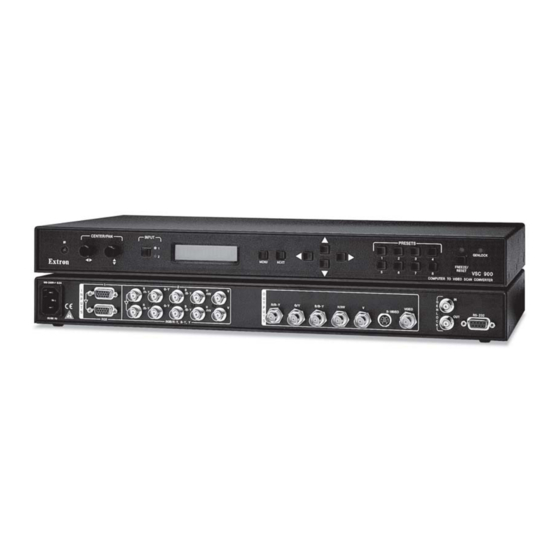
VSC 900 COMPUTER TO VIDEO SCAN CONVERTER Figure 2-7 — VSC 900/900D front panel features Infrared remote sensor — This sensor is used to receive infrared (IR) signals from the IR remote control. The IR remote control must be pointed directly at this sensor for best results. -
Page 18: Menus, Configuration, And Adjustments
The default menus appear on the LCD when no adjustments are actively being made. They cycle between the screen showing the name of the VSC (VSC 900/ 900D) and the screen that shows the horizontal and vertical frequencies of the input signal, as shown below. -
Page 19: Auto Imaging Menu (Auto Image)
Exit NEXT MENU Menu Figure 2-10 — Main menus for the VSC 900/900D Auto Imaging menu (Auto Image) The following flowchart illustrates the auto imaging feature. Pressing the Next button will display the submenu and automatically size and center the displayed image to fill the output screen. -
Page 20: Output Configuration Menu (Output Config)
The pedestal for NTSC video format may be turned on or off. See the following note. Rotate the horizontal Adjust knob ( ) or vertical Adjust knob ( ) to turn the pedestal on or off. 2-12 VSC 900/900D • Installation and Operation... -
Page 21: Set Pal Pedestal Submenu (Setup Pal)
Flicker control Horizontal filter Encoder NEXT Sharpness control Figure 2-13 — VSC 900/900D Filters menu Flicker filter adjustment submenu (Flicker) Use the Cursor buttons to select a flicker filter level to reduce display output flicker. Horizontal filter adjustment submenu (H Filter) Use the Cursor buttons to select a horizontal filter level to reduce loss of detail in the scan converted video image. -
Page 22: Size And Zoom Menu (Size/Zoom)
• Off (default) • RGB (default) • Color Bars • YUV • 32x24 Crosshatch • 4x4 Crosshatch • Gray Scale Input Atten. NEXT Input Attenuation level • Default is 0 Figure 2-15 — Advanced menu 2-14 VSC 900/900D • Installation and Operation... -
Page 23: Test Pattern Submenu
Horizontal phase and Subcarrier phase • Default is 128 Figure 2-16 — VSC 900/900D Genlock menu Horizontal and Subcarrier Phase submenu (H Phase Sub) Use the left/right or up/down Cursor buttons to adjust the horizontal phase and color subcarrier phase, respectively. See Genlock and Vertical Interval Switching in this chapter. -
Page 24: Additional Functions
In addition to the main menu system, there are several other functions that are featured by the VSC 900/900D: image centering, image freezing, unit reset to factory defaults, input reset to return the input to the factory default settings, and executive mode to disable the front panel controls. -
Page 25: Unit Reset Function
If you wait too long before pressing the Next button, the freeze mode will be enabled. You will need to press the Freeze/Reset button a second time to disable the freeze mode. VSC 900/900D • Installation and Operation 2-17... -
Page 26: Executive Mode
Executive mode may be enabled at any time and while in any menu. Press again to disable executive mode. Executive Mode Enabled Executive Mode Disabled Figure 2-22 — Executive mode 2-18 VSC 900/900D • Installation and Operation... -
Page 27: Presets
(horizontal frequency between 24 kHz and 70 kHz, and a vertical frequency of 50 Hz to 120 Hz). Call Extron’s customer support hotline if needed. Be prepared to discuss the steps you have taken and the equipment involved. VSC 900/900D • Installation and Operation 2-19... - Page 28 VSC. Ensure that the baud rate (9600 baud) and There is no response to communication protocol are set correctly. commands from the RS-232 controller. 2-20 VSC 900/900D • Installation and Operation...
-
Page 29: Vsc Infrared Remote Control
Preset button. Use the Zoom button to zoom in and zoom out of an image. The preset feature is available through RS-232 commands, VSC front panel controls, and the IR remote. VSC 900/900D • Installation and Operation 2-21... - Page 30 Installation and Operation, cont’d 2-22 VSC 900/900D • Installation and Operation...
-
Page 31: Chapter 3 • Serial Communication
VSC 900/900D Chapter Three Serial Communication RS-232 Programmer’s Guide Control Software for Windows Firmware Upgrade Through the Extron Website... -
Page 32: Rs-232 Programmer's Guide
When the scan converter receives a valid SIS command, it executes the command and sends a response to the host device. If the VSC 900/900D is unable to execute the command because the command is invalid or it contains invalid parameters, it returns an error response to the host. -
Page 33: Using The Command/Response Tables
The default value for horizontal and vertical size is 0512. The default values for the horizontal and vertical shift are 2048 and 1024, respectively. The actual minimum and maximum values will vary and are based on the incoming scan rate. VSC 900/900D • Serial Communication... - Page 34 Make the picture smaller. Horizontal filter Set a specific filter value Set the horizontal detail level. Increment up Increase horizontal detail. Increment down Decrease horizontal detail. View the filter level Show the horizontal detail level. VSC 900/900D • Serial Communication...
- Page 35 Query firmware version number x.xx Show the firmware version. Request part number Request VSC 900 part number 60-478-01 Show the VSC 900’s part #. Request VSC 900D part number N/nI 60-478-02 Show the VSC 900D’s part #. Request information Display information •...
- Page 36 Example: 64 15# Attn 64 Example: Set the current input’s attenuation to 64. Auto imaging Set the VSC to auto image 55 # Automatically center and size the image to fill the display screen. VSC 900/900D • Serial Communication...
-
Page 37: Control Software For Windows
Follow the instructions that appear on the screen. By default the installation creates a C:\VSC 900 directory, and it places two icons (VSC 900 Control Pgm and VSC 900 Help) into a group or folder named “Extron Electronics”. Using the control program Many items found in the VSC 900 Control Program are also accessible via front panel controls and the LCD menus described in chapter two. -
Page 38: Using The Help Program
Using the help program For information on program features, press the F1 computer key, or click on the Help menu from within the VSC 900 Control Program, or double-click on the VSC 900 Help icon in the Extron Electronics group or folder. -
Page 39: Firmware Upgrade Through The Extron Website
The VSC 900/900D’s firmware may be upgraded by going to the Extron website, downloading the latest firmware to the PC, then uploading and installing the new firmware from the PC to the VSC 900/900D via the scan converter’s RS-232 port. The whole process takes only a few minutes and is very simple. - Page 40 Serial Communication, cont’d 3-10 VSC 900/900D • Serial Communication...
- Page 41 VSC 900/900D Appendix Appendix Specifications Included Parts Accessories Firmware Upgrade Chip Installation Serial Digital Interface (SDI) Output Card Installation...
-
Page 42: Specifications
Standards ........NTSC 3.58, PAL Input level ........1.5 V to 5.0 Vp-p Output level ........TTL: 5.0 Vp-p, unterminated Input impedance ......600 ohms Output impedance ....... 75 ohms Max input voltage ......5.0 Vp-p Polarity .......... Negative VSC 900/900D • Appendix... - Page 43 Listings .......... UL, CUL Compliances ......... CE, FCC Class A, VCCI, AS/NZS, ICES MTBF ..........30,000 hours Warranty ........3 years parts and labor All nominal levels are at ±10%. Specifications are subject to change without notice. VSC 900/900D • Appendix...
-
Page 44: Included Parts
Appendix, cont’d Included parts These items are included in each order for a VSC 900/900D: Included parts Part number VSC 900 (1) 60-478-01 VSC 900D (1) 60-478-02 Rack mounting kit 70-077-03 IEC power cord Tweeker (small screwdriver) VSC 900/900D User’s Manual... -
Page 45: Firmware Upgrade Chip Installation
Firmware Upgrade Chip Installation In some cases the VSC 900/900D’s firmware may require replacement with an updated version. There is one user-replaceable firmware chip: U1. The number is printed on the circuit board. We recommend that you send the unit to Extron for service and updates. - Page 46 Gently, but firmly, press the chip into place in the socket. Replace the top cover on the VSC, and fasten it with the screws that were removed in step 3. Rack/furniture mount the scan converter, connect the input/output cables, and reconnect the AC power cord. VSC 900/900D • Appendix...
-
Page 47: Serial Digital Interface (Sdi) Output Card Installation
20 pins on the main circuit board. Be sure to align the pins properly, in order to prevent bending the pins, before pressing the SDI card firmly in place against the standoff. The mounting hole on the SDI card should now be directly over the standoff. VSC 900/900D • Appendix... - Page 48 Replace the top cover on the VSC, and fasten it with the screws that were removed in step 3. Rack/furniture mount the scan converter, connect the input/output cables, and reconnect the AC power cord. VSC 900/900D • Appendix...
- Page 49 Extron’s Warranty Extron Electronics warrants this product against defects in materials and workmanship for a period of three years from the date of purchase. In the event of malfunction during the warranty period...
- Page 50 Kyodo Building Anaheim, CA 92805 3821 AH Amersfoort PM Industrial Building 16 Ichibancho The Netherlands Singapore 368363 Chiyoda-ku, Tokyo 102-0082 Japan 714.491.1500 +31.33.453.4040 +65.6383.4400 +81.3.3511.7655 www.extron.com Fax 714.491.1517 Fax +31.33.453.4050 Fax +65.6383.4664 Fax +81.3.3511.7656 © 2005 Extron Electronics. All rights reserved.
Need help?
Do you have a question about the VSC 900 and is the answer not in the manual?
Questions and answers