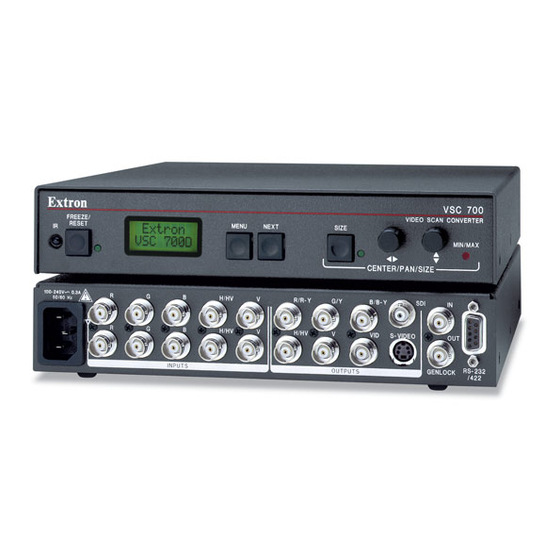
Extron electronics VSC 700 User Manual
Sdi output card
Hide thumbs
Also See for VSC 700:
- Datasheet (4 pages) ,
- Specifications (2 pages) ,
- User manual (31 pages)
Summary of Contents for Extron electronics VSC 700
- Page 1 Vertrieb von CAMBOARD Electronics User’s Guide VSC 700/900 SDI Output Card 70-065-02 Upgrade Kit 68-735-01 Rev. A Printed in the USA www.camboard.de Tel. 07131 911201 ce-info@camboard.de 09 03 Fax 07131 911203...
- Page 2 Remove 14 screws from the top and sides of the cover (figure 1) of the VSC 900. The VSC 700 has 12 top and side cover screws plus 9 rear panel screws and 2 jack screw nuts (RS-232/422 connector).
- Page 3 After following the instructions in “Cover removal” to remove the cover, do the following: Locate the SDI card standoff located near the middle rear (VSC 900) or left rear (VSC 700) portion of the main circuit board (looking from above with the front panel nearest to you).
- Page 4 Anaheim, CA 92805 3821 AH Amersfoort The Netherlands Singapore 368363 Chiyoda-ku, Tokyo 102-0074 Japan 714.491.1500 +31.33.453.4040 +65.6383.4400 +81.3.3511.7655 www.extron.com Fax 714.491.1517 Fax +31.33.453.4050 Fax +65.6383.4664 Fax +81.3.3511.7656 www.camboard.de Tel. 07131 911201 ce-info@camboard.de © 2003 Extron Electronics. All rights reserved. Fax 07131 911203...


Need help?
Do you have a question about the VSC 700 and is the answer not in the manual?
Questions and answers