Proxim ORiNOCO AP-4000MR-LR Quick Install Manual
Hide thumbs
Also See for ORiNOCO AP-4000MR-LR:
- Quick install manual (28 pages) ,
- Specifications (3 pages) ,
- Datasheet (2 pages)

Related Manuals for Proxim ORiNOCO AP-4000MR-LR


Summary of Contents for Proxim ORiNOCO AP-4000MR-LR
- Page 1 Quick Install Guide ORiNOCO AP-4000MR-LR ORiNOCO AP-4900MR-LR Part Number 73305/2 (Print version) Part Number 73307/2 (CD version)
-
Page 2: Table Of Contents
Notices © 2007 Proxim Wireless Corporation. All rights reserved. Covered by one or more of the following U.S. patents: 5,231,634; 5,875,179; 6,006,090; 5,809,060; 6,075,812; 5,077,753. This User Guide and the software described in it are copyrighted with all rights reserved. No part of this publication may be... -
Page 3: Introduction
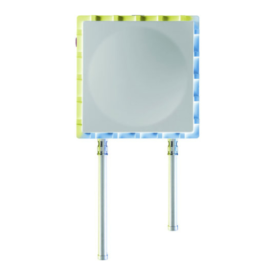
iNtroductioN The AP-4000MR-LR and AP-4900MR-LR are ruggedized tri-mode APs optimized for outdoor deployments. They are equipped with the following embedded radios: ▪ AP-4000MR-LR: One embedded 5.8 GHz (802.11a) radio and one embedded 2.4 GHz (802.11b/g) radio, enabling simultaneous support of 802.11a, 802.11b, and 802.11g clients. The unit also supports Mesh operation on either the 2.4 or 5.8 GHz band. - Page 4 Safety and Regulatory Compliance Guide on the installation CD. Figure 1: AP-4000MR-LR Unit (Dual LEDs and Serial Connection) Figure 2: AP-4000MR-LR FC Unit (Single LED and No Serial Connection) Page 4 Copyright © 2007 Proxim Wireless...
- Page 5 Figure 3: AP-4900MR-LR Unit (Dual LEDs and Serial Connection) Figure 4: AP-4900MR-LR FC Unit (Single LED and No Serial Connection) All rights reserved Page 5...
-
Page 6: Package Contents
Installation CD (1 ea.) Power Injector and Cord (1 ea.) Cable Termination Kit Kit includes: A. RJ45 connectors (2) B. Sealing caps (2) C. Lock nut D. Sealing nut E. Grounding screws (2) Page 6 Copyright © 2007 Proxim Wireless... - Page 7 Mounting Kit Kit includes the following: A. Mounting bracket for wall/pole B. Extension arm C. Mounting plate to enclosure D. Mounting bracket for pole mounting Mounting Hardware The following mounting hardware is included with mounting kit: Qty. Description 6 ea Plain washer #5/16 2 ea.
-
Page 8: Hardware And Software Installation
– UL-Listed/ITE (NWGQ) – Limited Power Source Output per UL/IEC 60950 – CE-marked – Approved for Power-over-Ethernet – Rated output, 48 Vdc/0.42 A – Pinout follows 802.3af standard for mid-span devices Page 8 Copyright © 2007 Proxim Wireless... -
Page 9: Step 1: Choose A Location
step 1: choose a location To make optimal use of the unit, you must find a suitable location for the hardware. The range of the radio unit largely depends upon the position of the antenna. Proxim recommends you do a site survey, observing the following requirements, before mounting the hardware. -
Page 10: Step 3: Assemble The Cable
This process will be described in Step 10: Weatherproof Connectors. Page 10 Copyright © 2007 Proxim Wireless... -
Page 11: Step 4: Assemble Mounting Hardware
step 4: assemble Mounting Hardware Attach the mounting plate (A) using the provided screws and washers (Torque 9 N∙m/75 in-lbs) Attach the extension arm (B) to mounting piece (A) with the screw, nut, and washers. Attach the mounting bracket (C) to extension arm (B) with the screw, nut, and washers provided. -
Page 12: Step 5: Mount The Unit
To pole-mount, insert the provided screws through bracket F. Fasten around the pole to bracket E and secure (Torque 11 N . m/100 in-lbs). To wall-mount the unit, mount bracket (E) to the wall using 4 screws (not provided), as shown. Page 12 Copyright © 2007 Proxim Wireless... -
Page 13: Step 6: Plug In The Cables
step 6: Plug in the cables Plug one end of the CAT5 cable (A) into the RJ45 jack of the unit (B). Note: On FC versions, connect the cable to the port labeled “J1 Antenna” on the power injector (not pictured). This port has 48 VDC power on the RJ45. Connect the free end of the CAT5 cable to the “Data and Power Out”... - Page 14 Note: On FC units, connect the cross-over cable between the network interface card in the PC and the and the RJ45 “J2 PC/Router” port on the power injector (not pictured). Page 14 Copyright © 2007 Proxim Wireless...
-
Page 15: Step 7: Power On The Unit
step 7: Power on the unit The power injector provides Power-over-Ethernet (PoE), supplying electricity and wired connectivity to the unit over a single 24 AWG CAT5 (diameter .114 to .250 inches/2.9 to 6.4 mm). The unit is not 802.3af-compatible. Always use the supplied power injector to ensure that the unit is powered properly. -
Page 16: Step 8: View Leds
Caution! Before applying power to the units, make sure that a proper load or antenna is connected to each N-female jack to minimize the chance of damaging the internal RF power amplifiers. Page 16 Copyright © 2007 Proxim Wireless... -
Page 17: Step 9: Tighten The Cables
step 9: tighten the cables Apply two wraps of Teflon tape around the threads of the unit’s RJ45 jack (A) in a clockwise direction. Make sure that the red rubber gasket is still seated in the sealing cap of the sealing cap/lock nut assembly (B). -
Page 18: Step 10: Weatherproof The Connectors
(not provided) over the rubber-based tape for further protection. Make sure the electrical tape also extends beyond the rubber- based tape to seal it. Repeat the weatherproofing procedure for other connectors as appropriate. Page 18 Copyright © 2007 Proxim Wireless... -
Page 19: Step 11: Install Documentation And Software
step 11: install documentation and software To install the documentation and software on a computer or network: Place the installation CD in a CD-ROM drive. The installer normally starts automatically. (If the installation program does not start automatically, click setup.exe on the installation CD.) Follow the instructions displayed on the installer windows. -
Page 20: Unit Initialization
Select Adapter button on the Scan List screen. ScanTool scans the subnet and displays all detected Access Points. The ScanTool’s Scan List screen appears, as shown in the following example. Page 20 Copyright © 2007 Proxim Wireless... - Page 21 Note: If your Access Point does not appear in the Scan List, click the Rescan button to update the display. If the unit still does not appear in the list, see the Troubleshooting chapter in the AP-4000MR-LR/4900MR-LR User Guide for suggestions. Note that after rebooting an Access Point, it may take up to five minutes for the unit to appear in the Scan List.
-
Page 22: Logging In
DHCP server or the static IP address you manually configured. See Using ScanTool section above for information on how to determine the unit’s IP address and manually configure a new IP address, if necessary. The login screen appears. Page 22 Copyright © 2007 Proxim Wireless... -
Page 23: Using The Setup Wizard
Enter the HTTP password in the Password field. Leave the User Name field blank. For new units, the default HTTP password is public. If you are logging on for the first time the Setup Wizard will launch automatically. Note Setup Wizard will not relaunch on subsequent logins. To force the Setup Wizard to launch upon login, click Management >... - Page 24 Follow the prompts provided by the Setup Wizard to perform an initial configuration of the AP. See the AP-4000MR-LR/4900MR-LR User Guide for more detailed Setup Wizard instructions and for advanced configuration instructions. Page 24 Copyright © 2007 Proxim Wireless...
-
Page 25: Software Updates
software uPdates Proxim periodically releases updated software for the AP-4000MR-LR/4900MR- LR on its support Web site, http://support.proxim.com. Proxim recommends that you check the Web site for the latest updates after you have installed and initialized the unit. Download the Software In your web browser, go to http://support.proxim.com. - Page 26 Click Commands > Reboot. Enter 0 in the Time to Reboot field. Click Note: For instructions on downloading the software via a TFTP Server or the CLI Interface, see the AP-4000MR-LR/4900MR-LR User Guide. Page 26 Copyright © 2007 Proxim Wireless...
-
Page 27: Frequencies And Bandwidths
frequeNcies aNd BaNdwidtHs Available channels vary depending on product. 2.4 gHz frequencies and Bandwidths (aP-4000Mr-lr/4900Mr-lr) Channel Center Frequency (MHz) 20 MHz 2412 2417 2422 2427 2432 2437 2442 2447 2452 2457 ... -
Page 28: Ghz Frequencies And Bandwidths (Ap-4900Mr-Lr Only)
4955 4960 4960 4965 4970 4975 4980 4985 = Occupied bandwidth for specified center frequency. Page 28 Copyright © 2007 Proxim Wireless... -
Page 29: Determining Your Hardware Variant
ideNtifyiNg your Hardware VariaNt You can verify which hardware version you are using through the HTTP Interface, as described below. status Page On the Status page, locate the product ID and serial number at the top of the page. If the serial number contains “FC” (as shown in the following figure), you are using the FC hardware variant. - Page 30 On the Monitor > Version page, locate the Hardware Inventory row. If the serial number listed in that row contains “FC” or if the variant listed in that row is “3” (as shown in the following figure), you are using the FC hardware variant. Page 30 Copyright © 2007 Proxim Wireless...
-
Page 31: Technical Services And Support
tecHNical serVices aNd suPPort If you are having trouble utilizing your Proxim product, please review the AP- 4000MR-LR/4900MR-LR User Guide and the additional documentation provided with your product. If you require additional support, please refer to the “Technical Services and Support”... - Page 32 www.proxim.com 2115 O’Nel Drive San Jose, CA (408) 731-2700...
Need help?
Do you have a question about the ORiNOCO AP-4000MR-LR and is the answer not in the manual?
Questions and answers