FLIR F-Series Installation Manual
Hide thumbs
Also See for F-Series:
- Installation manual (37 pages) ,
- Installation manual (22 pages) ,
- Installation manual (62 pages)
Table of Contents
Advertisement
Quick Links
Advertisement
Table of Contents

Related Manuals for FLIR F-Series


Summary of Contents for FLIR F-Series
- Page 1 Installation Manual F-Series...
- Page 2 © 2013 FLIR Commercial Systems, Inc. All rights reserved worldwide. No parts of this manual, in whole or in part, may be copied, photocopied, translated, or transmitted to any electronic medium or machine readable form without the prior written permission of FLIR Commercial Systems, Inc.
-
Page 3: Table Of Contents
1.6.4 Serial Connection .................... 1-7 1.7 Serial Communications Overview ................1-8 1.7.1 Serial Communications Settings - Hardware DIP Switches ......1-8 1.8 F-Series Camera Specifications ................1-11 Basic Operation and Configuration 2.1 Nexus IP Camera ...................... 2-1 2.1.1 Nexus Server Configuration ................2-1 2.1.2 Serial and/or IP Communications .............. - Page 4 Table of Contents 2.6.3 Security Settings .................... 2-14 2.6.4 Configuration File ................... 2-15 2.7 Thermal Imaging Overview ..................2-16 2.8 Troubleshooting Tips ....................2-18 2.9 General Errors ......................2-21 2.10 Restoring the Factory Settings ................2-23 2.11 Setting the IP address on a Windows PC .............. 2-24 Serial Address: Decimal To Binary Conversion 3.1 Address Conversion Table ..................
-
Page 5: F-Series Camera Installation
Camera Overview The F-Series camera is both an analog and an IP camera. The video from the camera can be viewed over a traditional analog video network or it can be viewed by streaming it over an IP network using MPEG-4, M-JPEG and H.264 encoding. -
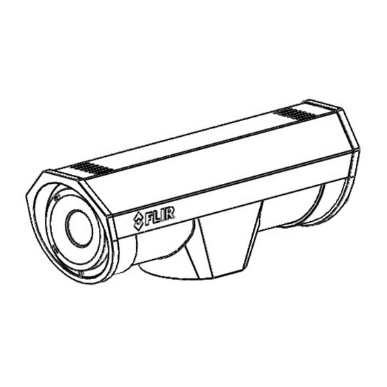
Page 6: Installation Overview
Remove before installing Figure 1-1: F-Series Camera The F-Series camera is intended to be mounted on a medium-duty fixed pedestal mount or wall mount commonly used in the CCTV industry. Cables will exit from the back of the camera housing. -
Page 7: Required Components
1.5.3 Camera Mounting F-Series cameras must be mounted upright on top of the mounting surface, with the base below the camera. The unit should not be hung upside down. The F-Series camera can be secured to the mount with three to five 1/4-20 threaded fasteners as shown below. -
Page 8: Removing The Back Cover
F-Series Camera Installation Not to scale Figure 1-2: F-Series Camera Mounting Holes Once the mounting location has been selected, verify both sides of the mounting surface are accessible. Use a thread locking compound such as Loctite 242 or equivalent with all metal to metal threaded connections. -
Page 9: Cable Glands And Spare Parts Kit
PT-Series back cover screws 1.5.7 Cable Gland Seal Inserts Ground The F-Series camera comes with two 3/4” NPT cable glands, each with a three hole gland seal Camera Power insert. Cables may be between 0.23" to 0.29" OD. Typically up to five cables may be needed. -
Page 10: Camera Connections
1.6.1 Connecting power The camera itself does not have an on/off switch. Generally the F-Series camera will be connected to a circuit breaker and the circuit breaker will be used to apply or remove power to the camera. If power is supplied to it, the camera will be in one of two modes: Booting Up or Powered On. -
Page 11: Video Connection
Pelco D, RS-422 standard, 9600 baud rate, 8/1/none, and address 1. Note Typical Bosch systems operate using a biphase connection and the FLIR cameras do not accept biphase signals directly. It may be necessary to install a biphase converter in order to use the Bosch protocol. -
Page 12: Serial Communications Overview
Note The serial communications parameters for the F-Series camera are set or modified either via hardware DIP switch settings or via software, through a web browser interface. A single DIP switch (SW102-9), Software Override determines whether the configuration comes from the hardware DIP switches or the software settings. - Page 13 F-Series Camera Installation If the Software Override DIP switch is set to the software position (as it is by default), all of the other DIP switches will be ignored, and configuration changes must be made through software. If the switch is set to the hardware position, all configuration settings related to serial communications are made with the DIP switches, and changes that are made via software (with a web browser) will be ignored.
- Page 14 F-Series Camera Installation Table 1-2: Dip Switch Settings—SW102 Settings Description Camera Control Protocol: This is the communication Bit 3 Bit 4 protocol selected for the system when operating over the Pelco-D serial port. The available protocols are Pelco-D and Bosch.
-
Page 15: F-Series Camera Specifications
F-Series Camera Installation F-Series Camera Specifications THERMAL CAMERA SPECS Resolution 160 x 120 320 x 240 640 x 480 Detector Type Long-Life, Uncooled VO× Microbolometer Pixel Pitch 25 μm 25 μm 17 μm Focal Length (lens/model dependent) 9 mm, 13 mm, 19 mm... - Page 16 F-Series Camera Installation 427-0030-00-12, version 170 Mar 2014 1-12...
-
Page 17: Basic Operation And Configuration
For a camera installed in an IP network, the camera will commonly be controlled over Ethernet by a PC or laptop running FLIR Sensors Manager (FSM) or a third-party Video Management System (VMS) software. FSM is an integral part of the Nexus architecture—it is a client program that communicates with the Nexus Server on the camera. -
Page 18: Serial Communications
(for example, any PC or device that will connect to the camera, any router or firewall that will carry the IP traffic, and so on). FLIR technical support can only provide limited support in this regard. -
Page 19: Test And Configuration Steps
Basic Operation and Configuration Even if using analog video and serial communications in the final installation, it is a good idea to test the IP communications when performing the bench test. If any image adjustments are necessary, they can be done using a web browser over the IP connection, and saved as power-on default settings. With the camera powered up, analog video can be tested at the BNC connectors. -
Page 20: Log Into The Camera Web Page
The Live Video page will be displayed, with a live image from the camera on the left part of the screen. Next to the FLIR logo along the top of the screen are some menu choices, including Live Video (the red text indicates it is selected), Help and Log Off. -
Page 21: Camera Control And Status
This same web interface is used with various FLIR thermal cameras; some are fixed mount cameras, such as the F-Series and FC-Series S cameras, and some have pan/tilt capabilities, such as the PT-Series and D-Series. -
Page 22: Help
If it is necessary to contact FLIR Technical Support for assistance, it will be helpful to have the information from this page (such as Software Version) on hand. -
Page 23: Running Fsm
2.4.1 Running FSM Run the FSM software by double clicking the FLIR Sensors Manager icon on the desktop, or click on the Windows Start button and select Programs > FLIR Sensors Manager > FLIR Sensors Manager. Initially the FLIR Sensors Manager splash screen will be displayed. After a brief while, the FSM main window will appear. - Page 24 Basic Operation and Configuration When the Discovery Panel is displayed, click Refresh. The FLIR camera will appear in the list of Discovered Sensors. The camera will be called “FLIR”, and the asterisk in parenthesis “(*)” indicates the camera has not been added to the list of Active Sensors on the right.
-
Page 25: Basic Camera Configuration
Basic Operation and Configuration Basic Camera Configuration The following procedures describe how to do the most common basic camera configuration steps, such as setting the camera IP address and hostname and changing the user passwords. To make these changes, it is necessary to login using the admin user account. Note In most installations, the only camera settings needed are available from the Live Video page (using Scene Presets or Polarity). -
Page 26: Maintenance Menu
Basic Operation and Configuration Maintenance Menu Initially, when the Maintenance page is selected, the Server Status page is displayed. The page provides an indication of the current server status (either running or stopped) and buttons for starting or stopping the server or for rebooting the system. Note, In order to make some configuration changes through the Maintenance menu, it is necessary to save the changes, then stop and restart the server to make the changes take effect. -
Page 27: Lan Settings
Basic Operation and Configuration 2.6.1 LAN Settings The LAN Settings page can be used to set the hostname, default gateway, and IP address for the camera. The default IP Address mode is static; the mode can also be set to DHCP. Once the IP address of the camera is changed, the PC may no longer be on the same network and therefore may not be able to access the camera until the IP address on the PC is changed also. -
Page 28: Services (Date And Time Settings)
Basic Operation and Configuration 2.6.2 Services (Date and Time Settings) The Services page is used to configure the date and time settings. The date, time, and time zone can be obtained from an NTP server, or can be entered manually. If the NTP mode is selected, the NTP server information can be entered. -
Page 29: Security Settings
Basic Operation and Configuration 2.6.3 Security Settings To maintain security of your systems set passwords for each of the three login accounts. user —The user account can only use the Live Video screen and controls. expert —The expert account can use the Live Video screen and the camera Setup screen. admin —The admin account can use all screens After each password is set and confirmed, select the Save button at the bottom (it may be necessary to scroll down the page). -
Page 30: Configuration File
Basic Operation and Configuration It is also possible to limit access to the camera from a client program (such as FSM) by IP address. To do so, in the Maintenance menu select Sensor, then Networking. Set the “Allow anonymous clients” parameter to No, and then add in the allowed addresses in the Remote Clients list and click Save. -
Page 31: Thermal Imaging Overview
Basic Operation and Configuration Thermal Imaging Overview When power is applied to the F-Series camera, a FLIR splash screen is displayed for less than two seconds, and then the camera outputs the live video image. No operator action or intervention is required and no configuration of the camera is necessary. - Page 32 The F-Series camera is a state-of-the-art thermal imaging system that will provide excellent night visibility and situational awareness, without any form of natural or artificial illumination. The system is easy to use, but it is useful to understand how to interpret what is displayed on the monitor.
-
Page 33: Troubleshooting Tips
If the camera still does not produce an image, contact the FLIR dealer or reseller who provided the camera, or contact FLIR directly (contact information is provided on the rear cover of this manual). - Page 34 FSM program. Typically when FSM runs for the first time, a pop-up notification may ask for permission to allow the FLIR Sensors Manager (fsm.exe) to communicate on the network. Select the check boxes (domain/private/public) that are appropriate for your network.
- Page 35 Basic Operation and Configuration In the Sensors Panel, if the camera is the active sensor, there will be an “(Active)” notification next to the name of the camera. Only one camera or sensor can be active at a time. To make the camera active, right click on the icon to the left of the camera name and select “Set Active”, or simply double-click on the icon.
-
Page 36: General Errors
When displaying video with FSM for the first time, the Windows Personal Firewall may ask for permission to allow the FLIR Video Player (vp.exe) to communicate on the network. Select the check boxes (domain/private/public) that are appropriate for your network. - Page 37 Use a high-quality video distribution amplifier when splitting the signal to multiple monitors. Image too dark or too light: By default the F-Series thermal camera uses an Automatic Gain Control (AGC) setting that has proven to be superior for most applications, and the camera will respond to varying conditions automatically.
-
Page 38: Restoring The Factory Settings
Basic Operation and Configuration 2.10 Restoring the Factory Settings The camera comes configured from the factory with default settings for the IP address (192.168.250.116), the login passwords, and all of the other configuration parameters (stored in a file called server.ini). In some cases, it may be necessary to restore the settings of the camera to the original factory settings. -
Page 39: Setting The Ip Address On A Windows Pc
Basic Operation and Configuration After the camera boots up, confirm the startup information is displayed on the analog monitor after approximately 90 seconds. For example: S/N: 1234567 IP Addr: 192.168.250.116 PelcoD (Addr:1): 9600 SW 2.11 Setting the IP address on a Windows PC To set the computer IP address in Windows, first connect the PC to a switch, or connect it to the camera and ensure the camera has power. - Page 40 Basic Operation and Configuration Step 2 Click to select the Local Area Connection then click Properties, as shown at the right. Click Properties Step 3 Select Internet Protocol Version 4 (TCP/IPv4) as shown. Then click Properties. Click to select Click Properties 2-24 427-0030-00-12 Version 170 Mar 2014...
- Page 41 Basic Operation and Configuration Step 4 Select Use the following IP address, then enter 192.168.250.xxx, where xxx is any number between 1-255, other than 116 (the camera default). Step 5 Set the Subnet mask to 255.255.255.0, then click OK. 427-0030-00-12 Version 170 Mar 2014 2-25...
- Page 42 Basic Operation and Configuration 427-0030-00-12, Version 170 Mar 2014 2-26...
-
Page 43: Serial Address: Decimal To Binary Conversion
Serial Address: Decimal To Binary Conversion Note, the order of the switches 1-8 is the reverse of the binary digits. For example, for address 1 the binary equivalent is 00000001 and the left-most switch (switch1) is on. Address Conversion Table Address Sw 2 Sw 3... - Page 44 Serial Address: Decimal To Binary Conversion 00011100 01011100 10011100 11011100 00011101 01011101 10011101 11011101 00011110 01011110 10011110 11011110 00011111 01011111 10011111 11011111 00100000 01100000 10100000 11100000 00100001 01100001 10100001 11100001 00100010 01100010 10100010 11100010 00100011 01100011 10100011 11100011 00100100 01100100 10100100 11100100 00100101...
-
Page 46: Goleta, Ca
FLIR Systems, Inc. 70 Castilian Drive Goleta, CA 93117 PH: + 1 805.964.9797 PH: + 1 877.773.3547 (Sales) PH: + 1 888.747.3547 (Support) FX: + 1 805.685.2711 www.flir.com Corporate Headquarters FLIR Systems, Inc. 27700 SW Parkway Ave. Wilsonville, OR 97070 PH: +1 503.498.3547...
Need help?
Do you have a question about the F-Series and is the answer not in the manual?
Questions and answers