
Related Manuals for FLIR TG267


Summary of Contents for FLIR TG267
- Page 1 USER MANUAL Automotive Diagnostic Thermal Camera Models TG267 and TG297 GlobalTestSupply www. .com Find Quality Products Online at: sales@GlobalTestSupply.com...
- Page 2 USER MANUAL Automotive Diagnostic Thermal Camera #NAS100014; r. AA/59807/59807; en-US GlobalTestSupply www. .com Find Quality Products Online at: sales@GlobalTestSupply.com...
-
Page 3: Table Of Contents
Operation ................7 Camera Power ............7 IR Camera and Thermometer ........7 High Temperature Switch (TG297)........8 Type-K Thermocouple Measurements (TG267) ....8 Visible Spectrum Camera ........... 10 Capturing and Working with Images......10 Programming Menu System ..........12 Menu System Basics ..........12 Main Menu .............. - Page 4 Table of contents 10.4 Measurement Specifications ........25 10.5 Measurement Analysis Specifications ......25 10.6 Type-K specifications (TG267 only) ......25 10.7 Configuration Specifications........26 10.8 Image Storage Specifications ........26 10.9 Digital Camera Specifications........26 10.10 Flashlight Specifications..........26 10.11 Laser Pointer Specifications ........
-
Page 5: Advisories
Advisories 1.1 Copyright ©2019, FLIR Systems, Inc. All rights reserved worldwide. No parts of the software including source code may be reproduced, transmitted, transcribed or translated into any language or computer language in any form or by any means, electronic, magnetic, optical, manual or otherwise, without the prior written permission of FLIR Systems. -
Page 6: Introduction
Introduction The FLIR TG267 and TG297 are Automotive Diagnostic Thermal Cameras which combine non-contact temperature measurement and thermal imaging into one troubleshooting tool to help you quickly find the source of heat-re- lated problems and spot potential faults when performing automotive mainte- nance and repair. -
Page 7: Safety
Safety 3.1 Safety Warnings and Cautions WARNING ⚠This symbol, adjacent to another symbol indicates the user must refer to the manual for further information. WARNING The instrument’s IP54 rating is only in affect when the top flap (covering the USB-C and Thermocouple jacks) is completely sealed. -
Page 8: Description
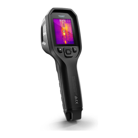
Description 4.1 Product Description Figure 4.1 Imaging IR Thermometer Description (TG297 pictured) 1. Display area 2. Return button (to back up in the menu system) 3. Laser pointer button 4. Up/Down Navigation buttons and Power button (long press)/Menu button (short press) 5. -
Page 9: Control Button Descriptions
Description 4.2 Control Button Descriptions Long press to power ON or OFF Short press to access the menu system Return button. Back out to previous screen in menus Press to scroll upward in the menus Press to scroll downward in the menus Press to activate the Laser pointer Pull trigger to capture camera image TRIGGER... - Page 10 Description 7. Camera image area 8. Center spot cross-hairs 9. Laser Pointer active 10. Center spot temperature measurement 11. Thermocouple measurement (TG267) #NAS100014; r. AA/59807/59807; en-US GlobalTestSupply www. .com Find Quality Products Online at: sales@GlobalTestSupply.com...
-
Page 11: Operation
Operation 5.1 Camera Power Power is supplied by a rechargeable lithium battery. Long press the power button (center) to switch the camera ON or OFF. If the camera does not power ON, charge the battery by connecting to an AC wall charger using the sup- plied USB-C cable. -
Page 12: High Temperature Switch (Tg297)
TG267. If the thermocouple does not include a range label, please contact FLIR technical support. - Page 13 Operation WARNING To avoid electrical shock, do not use this instrument when working near voltages > 24V AC/DC. Do not allow the thermocouple to touch live circuitry. WARNING To avoid damage and burns, do not make temperature measurements in microwave ovens. CAUTION Repeated flexing can break the thermocouple leads.
-
Page 14: Visible Spectrum Camera
Operation 5. If the thermocouple is not connected when the Type-K mode is selected, the display will show dashes in place of a reading. If the measurement is out of range, the display will show ‘OL’. 6. To find the optimum emissivity setting for a given surface, take an IR tem- perature measurement and then take a Type-K measurement. - Page 15 Operation 4. To send/view/delete images, access the Gallery mode in the main menu. In the Gallery, scroll through the stored images with the arrows and open an image with the MENU button. Once an image is opened, press MENU again to see the SEND/CANCEL/DELETE/DELETE ALL IMAGES menu. Select the SEND command to transmit an image, via Bluetooth®, to a paired mobile device.
-
Page 16: Programming Menu System
Programming Menu System 6.1 Menu System Basics Short press the MENU button to access the menu system. Use the MENU button to switch settings ON or OFF, use the Return button to move to the pre- vious screen, and use the arrows to scroll. The MENU button is used in some cases to confirm settings. - Page 17 Programming Menu System 1. Image Modes: Press MENU at IMAGE MODES and use the arrow buttons to select VISIBLE IMAGE or THERMAL PLUS VISIBLE IMAGE (MSX®). 2. MSX® Alignment: While at the Image Mode menu you can adjust the MSX® alignment so that the thermal image and the visible image are aligned accurately.
-
Page 18: Settings Sub-Menu
Programming Menu System 3. Colors: Press MENU at the Colors menu and use the arrow buttons to se- lect a color palette: Iron, Rainbow, White hot, Black hot, Arctic, or Lava. Press MENU to confirm selection. • SETTINGS: Press MENU to access the Settings sub-menu (see below): 6.3 Settings Sub-Menu •... - Page 19 At the Custom Val- ue setting, press MENU and then use the arrows to select the emissivity value; press MENU to confirm. 3. Thermocouple: Press MENU to toggle the Thermocouple mode ON/OFF (TG267 only). • DEVICE SETTINGS #NAS100014; r. AA/59807/59807; en-US GlobalTestSupply www.
- Page 20 Programming Menu System 1. Bluetooth®: Press MENU to switch Bluetooth® ON or OFF. See Section 7, Bluetooth®, and Section 5.6, Capturing and Working with Images, for details. 2. Laser: Press MENU to enable/disable the Laser pointer. When enabled, you can use the Laser pointer button to switch ON the Laser pointer. 3.
- Page 21 Programming Menu System 4. Auto Power OFF (APO): Use the arrows to scroll and MENU to select the desired APO time (5/15/30 minutes). Set to ‘Never’ to disable APO. • GENERAL SETTINGS 1. Temperature Unit: Use the arrows and the MENU button to select °C or °F. 2.
- Page 22 Programming Menu System 3. Language: Use the arrows to scroll and the MENU button to select a language. 4. System Info: Scroll to desired topic: Model Number, Serial Number, Software Level, Revision, Battery status (%), and remaining Internal Storage Capacity. •...
- Page 23 Programming Menu System #NAS100014; r. AA/59807/59807; en-US GlobalTestSupply www. .com Find Quality Products Online at: sales@GlobalTestSupply.com...
-
Page 24: Bluetooth® Communication And Flir Tools
Bluetooth® Communication and FLIR Tools™ To connect to a mobile device running the FLIR Tools™ Mobile App, turn on the mobile device and start the FLIR Tools™ Mobile App (download the mo- bile App from the Google Play™ store, the Apple App store, or here: https://www.flir.com/products/flir-tools-app/). - Page 25 Bluetooth® Communication and FLIR Tools™ WARNING Changes or modifications not expressly approved by the party responsible for compliance could void the user’s authority to operate the equipment. #NAS100014; r. AA/59807/59807; en-US GlobalTestSupply www. .com Find Quality Products Online at: sales@GlobalTestSupply.com...
-
Page 26: Field Firmware Updates
System firmware by first downloading an update file from the FLIR website and then transferring the file to the camera via USB. Connect to a PC using a USB-C cable. Firmware updates are available from https://support.flir.com. -
Page 27: Maintenance
Clean the lenses with a high-quality lens cleaner. 9.2 Battery Considerations and Service The rechargeable lithium battery is not user-serviceable. Please contact FLIR support for service instructions: https://support.flir.com. For best results, charge the battery immediately after seeing a low battery in- dication using the supplied USB-C cable (with an AC wall charger, not sup- plied). -
Page 28: Specifications
Specifications 10.1 Imaging and Optical Specifications IR resolution 160 x 120 pixels Digital image enhancement Included Thermal Sensitivity /NETD < 70 mK Field of View (FOV) 57° x 44° Minimum focus distance 0.89 ft. (0.3 m) Distance-to-Spot ratio 30:1 Dual range operation (TG297) Range 1: <... -
Page 29: Measurement Specifications
Specifications 10.4 Measurement Specifications Object temperature range TG267: –13 ~ +716℉ (–25 ~ +380℃) TG297: –13 ~ +1886℉ (–25 ~ +1030℃) Accuracy at ambient temperature: 15 ~ -13℉ ~ 32℉ (-25℃ to 0℃): ± 7.0℉ (3.0℃) 35℃ (59 ~95℉) 32℉ ~ 122℉ (0℃ ~ 50℃): ± 5.0℉ or ±... -
Page 30: Configuration Specifications
Please do not exceed the specified range printed on the thermocouple label. To measure higher or lower than the range of the supplied thermocouple, please use a Type-K thermocouple rated for the desired range. Contact FLIR for additional information 10.7 Configuration Specifications... -
Page 31: Laser Pointer Specifications
Specifications Rated power 0.5 W Light output 100 Lumens 10.11 Laser Pointer Specifications Laser type DOE (Diffractive optical elements) Laser function Indicates the size of the measurement area (circular target) Laser class Class I 10.12 Data Communication and Interface Specifications Interfaces USB 2.0 and Bluetooth®... - Page 32 Specifications Operating temperature 14 ~ 113℉ (-10 ~ 45℃) Storage temperature -22 ~ 131℉ (-30 ~ 55℃) Humidity (operating and storage) 0 ~ 90% Relative Humidity (RH) 32 ~ 98.6℉ (0 ~ 37℃) 0 ~ 65% RH 98.6 ~ 113℉ (37 ~ 45℃) 0 ~ 45% RH 113 ~ 131℉...
-
Page 33: Physical Specifications
Specifications 10.15 Physical Specifications Weight 13.9 oz. (0.39 kg) Size (L x W x H) 8.3 x 2.5 x 3.2 in. (210 x 64 x 81 mm) Accessory mount UNC ¼”-20 10.16 Included Equipment Standard equipment Camera, USB-C cable, printed Quick Start Guide, Lanyard, Carry Pouch #NAS100014;... -
Page 34: Appendices
Appendices 11.1 Emissivity Factors for Common Materials Material Emissivity Material Emissivity Asphalt 0.90 ~ 0.98 Cloth (black) 0.98 Concrete 0.94 Skin (human) 0.98 0.96 Leather 0.75 ~ 0.80 Cement 0.90 0.96 Sand Charcoal (powder) Soil 0.92 ~ 0.96 Lacquer 0.80 ~ 0.95 Water 0.92 ~ 0.96 Lacquer (matt) - Page 35 Appendices puddles of water and other cold objects appear dark (or cool). Scenes with fa- miliar objects will be easy to interpret with some experience. Infrared energy is part of a complete range of radiation called the electromag- netic spectrum. The electromagnetic spectrum includes gamma rays, X-rays, ultraviolet, visible, infrared, microwaves (RADAR), and radio waves.
Need help?
Do you have a question about the TG267 and is the answer not in the manual?
Questions and answers