Table of Contents
Advertisement
Quick Links
Advertisement
Table of Contents

Subscribe to Our Youtube Channel
Related Manuals for XVision XSD27ZIR


Summary of Contents for XVision XSD27ZIR
-
Page 1: User Manual
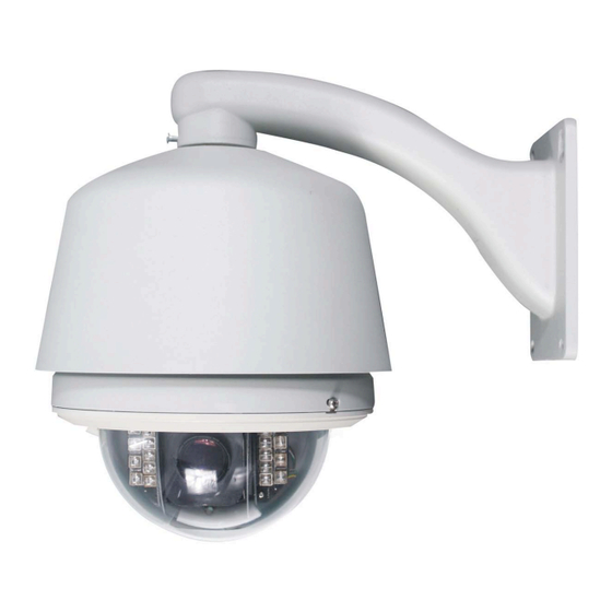
XSD27ZIR Day/Night 550/600 TVL IR Speed Dome Camera with 27x Optical Zoom, 50 Metres IR Night Vision & Power Supply USER MANUAL P l e a s e r e a d t h i s m a n u a l b e f o r e y o u i n s t a l l o r s t a r t u s i n g t h e X S D 2 7 Z I R S p e e d D o m e... -
Page 2: Table Of Contents
XSD27ZIR CONTENTS FEATURES····································································· 3 CAMERA PARAMETERS··············································· 19 DECLARATION ······························································ 4 White Balance················································· 19 Precaution ························································ 4 BLC Mode······················································· 19 Warnings ·························································· 4 PAN/TILT PARAMETERS··············································· 20 INSTALLATION PREPARATION······································· 5 Auto Stop Time ··············································· 20 Tool List···························································· 5 Speed Amplify················································· 20 Cables ······························································ 5 Proportional P/T ··············································... -
Page 3: Features
XSD27ZIR FEATURES Product Features Day/Night Camera with 18x SRLEDs for an IR Multiple RS485 protocols range of 60m On-Screen Display can be customized to suit user Offers High Resolution 550/600 TVL images OSD Menu for Programmable Functions ... -
Page 4: Declaration
XSD27ZIR TECHNICAL SPECIFICATIONS Image Sensor 1/4” Super HAD Image Resolution 550/600 TVL Lens 3.9 to 105.3mm Zoom Zoom Speed 3.9 to 6.3 seconds Angle of View 1° to 60° Sync system Internal/external Min. Illumination 0 Lux with IR on S/N Ratio >48db... -
Page 5: Installation Preparation
XSD27ZIR I N S T A L L A T I O N P R E P A R A T I O N TOOL LIST: Following tools may be needed for the installation: Screws and nuts Philips screw driver... -
Page 6: Mount Type
XSD27ZIR MOUNT TYPE W A L L M O U N T P O L E M O U N T (supplied) (optional accessory) C O R N E R M O U N T P E N D A N T M O U N T... -
Page 7: Installation Guide
XSD27ZIR INSTALLATION GUIDE WALL MOUNT Check to make sure the wall surface is firm and does not flake off. The wall must be able to withstand 8 times weight of the dome and its fixtures. 1. Mark mounting position 2. Install bracket. -
Page 8: Corner Mount
XSD27ZIR 6. Install black liner and Pan/Tilt Module 7. Install down cover Unscrew the two M4 screw on down cover ring. Push up the down cover into the housing and then fasten down cover with two M4 screws. NOTE: Apply lube to the O-ring for external mounting C O R N E R M O U N T Check carefully to make sure the wall is firm and does not peel off. - Page 9 XSD27ZIR 5. Set dome ID, baud rate and protocol Set dome ID, bard rate and protocol by configuring DIP switches (see APPENDIX I ). NOTE: Remove the packing sponges 6. Connect cables. Plug cables into corresponding sockets on circuit board. Reinstall the circuit board and turn on the power.
-
Page 10: Pole Mount
XSD27ZIR P O L E M O U N T The Pole mount can be installed on pole with diameter of 130 to150mm ( 5.12” to 6”) Install base. Install bracket. Feed the Power/RS485/ Video cables through the central Put cables through the cavity of bracket and fasten it on base. -
Page 11: Pendent Mount
XSD27ZIR 6. Install black liner and Pan/Tilt Module 7. Install down cover Unscrew the two M4 screw on down cover ring. Push up the down cover into the housing and then fasten down cover with two M4 screws. NOTE: Apply lube to the O-ring for external mounting P E N D E N T M O U N T For low ceiling installations, dome can be mounted directly into the base flange. - Page 12 XSD27ZIR 5. Set dome ID, baud rate and protocol Set dome ID, bard rate and protocol by configuring DIP switches (see APPENDIX I). NOTE: Remove the packing sponges 6. Connect cables. Plug cables into corresponding sockets on circuit board. Reinstall the circuit board and turn on the power. Turn off the power after checking.
-
Page 13: System Connection
XSD27ZIR S Y S T E M C O N N E C T I O N... -
Page 14: Operation Instruction
XSD27ZIR OPERATION INSTRUCTIONS The Speed Dome can be controlled through combination of hot keys on a keyboard controller. It can also be controlled through the OSD menu. The OSD menu can be activated by preset #95 call or double calling preset 1 (call twice within 5 seconds). Preset calling can be done through a keyboard controller or any other device (e.g. -
Page 15: Menu Operation
XSD27ZIR MENU OPERATION 2. Move the joystick down to point the cursor to SELECTING A MENU ITEM <Camera >, move the joystick right to select it. Select BLC MODE in the same way In the main menu, the cursor flashes on the left side. Move the joystick up or down to point to the desired item. -
Page 16: System Menu
XSD27ZIR SYSTEM MENU move joystick up or down to select desired ID number. SYSTEM MENU OPTIONS Move the joystick left to save the settings. <Main Menu> <System > Site Info <Name> Display Setup <Name> refers to the title of the dome. Assign a dome Bootup Screen name to remember which dome it is. -
Page 17: Boot-Up Screen
XSD27ZIR BOOT-UP SCREEN SET DEFAUT <Main Menu> <System Info> <Set Default> <Main Menu> <System > <Bootup Screen> Select <Set Default> to restore factory default settings. Camera S/N : 8888888888 List of Default Settings : Camera ID : 001... -
Page 18: Lens Parameters
XSD27ZIR LENS PARAMETERS MENU LEN MENU OPTIONS AI RESUME TIME <Main Menu> <Lens> <Main Menu> <Lens> < AI Resume Time > Joystick AF/AI : Both Light goes through the iris and reaches the CCD to form AF Resume Time: Off an image. -
Page 19: Camera Parameters
XSD27ZIR CAMERA PARAMETERS MENU CAMERA MENU OPTIONS BLC MODE <Main Menu> <Camera> <Main Menu > <Camera> <BLC Mode> White Balance: Auto R Gain (000-255), Adjusts RED color depth. BLC Mode B Gain (000-255), Adjusts BLUE color depth. -
Page 20: Pan/Tilt Parameters
XSD27ZIR PAN/TILT PARAMETERS PAN TILT MENU OPTIONS PROPORTIONAL P/T <Main Menu> <Pan/Tilt> <Main Menu> <Pan/Tilt> <Proportional P/T> The dome moves at a speed of certain degree per Auto Stop Time : Off second. Objects on screen move much faster in wide Speed Amplify : Off scope than in tele-scope. -
Page 21: Auto Running
XSD27ZIR AUTO RUNNING AUTO RUNNING MENU OPTIONS Call Preset 1 To Confirm………. <Main Menu> <Auto Running> Move the camera to the desired position and zoom to a Preset suitable level, call preset 1 to save the current preset. Tour ... -
Page 22: Cruise
XSD27ZIR <Edit> NOTE: If the speed dome has been zoomed in and <Cruise> is selected, the camera will keep that zoom Edit presets and corresponding dwell times in a tour as throughout the camera’s movement. follows: The speed dome has a maximum of 4 cruise lines. -
Page 23: Zone
XSD27ZIR <Record> Call Preset 1 To Select to Record a pattern. The following menu will pop Confirm… Move to the desired point and call preset 1 to confirm. Call Preset 1 To Confirm… <Pan Speed> X/100 Select to set the pan speed (camera movement speed). -
Page 24: Appendix I: Dip Switch Setting
XSD27ZIR APPENDIX I: DIP SWITCH SETTINGS This is the guide for setting protocol, baud rate, dome address, video cable type and resistor jumper. DIP Switch position The corresponding Dip Switch positions are shown below: Switch Num ber Protocol ERNITEC... -
Page 25: Dome Address Setting
XSD27ZIR Dome Address Setting The control commands contain target dome’s ID. The dome only reacts to the command sent to its own address or broadcast address. Each dome should be assigned an address. Four kinds of IDs are applicable for domes: 1. -
Page 26: Address Setting Chart
XSD27ZIR 4. Address setting chart Soft Soft 26 ... - Page 27 XSD27ZIR Soft Soft 27 ...
- Page 28 XSD27ZIR Soft Soft 28 ...
-
Page 29: Resistor Jumper Setting
XSD27ZIR Resistor Jumper Setting When choosing the first and second pins in JP02, the RS485 bus needs two 120-Ohm resistors at both ends. 120-Ohm termination resistor is connected. Set the 120-Ohm resistors of the two devices (keyboard or dome) at the farthest distance on RS485 bus. The default When choosing the second and third pins in JP02, the setting is OFF. -
Page 30: Transmission Chart
XSD27ZIR APPENDIX II: WIRE DIAMETER & TRANSMISSION CHART The transmission distances listed below are the farthest ones recommended for each given wire diameter when the 24V AC voltage loss ratio is below 10% (for equipment powered by AC, the maximum voltage loss ratio allowed is 10%). -
Page 31: Appendix Iii: Rs485 Bus Basic Knowledge
XSD27ZIR APPENDIX III RS485 BUS BASIC KNOWLEDGE Basic Property Best Practice RS485 Bus is specified by RS485 standards. It is of In some circumstances a star configuration connection is half-duplex data transmission cables with characteristic required. The termination resistors must be connected to impedance as 120. -
Page 32: Appendix Iv Trouble Shooting
XSD27ZIR APPENDIX IV TROUBLE SHOOTING Problem Cause Solution No movements, Red LED on circuit board is off: Check the power connection and no video after outlet make sure they are working power on properly. There is no AC power connected to the PCB Board. -
Page 33: Appendix V: Lightning & Surge Protection
XSD27ZIR APPENDIX V: LIGHTNING & SURGE PROTECTION The product features TVS lightning proof technology to prevent from damage by lightning strike below 1500W and impulse signals such as surge. It is necessary to abide by the following precautions to ensure electrical safety based on practical circumstances: Keep the communication cables at least 50 meters away from high voltage equipment or cables. -
Page 34: Appendix Vi Warranty
APPENDIX VI WARRANTY TECHNICAL SUPPORT: For Technical Support for any Xvision product please contact your local distributor. LIMITED WARRANTY: This product is supplied with a 1 Year warranty. The Warranty excludes products that have been misused, (including accidental damage) and damage caused by normal wear and tear. In the unlikely event that you... - Page 35 XSD27ZIR...
- Page 36 XSD27ZIR Manufactured exclusively for Xvision - www.x-vision.co.uk UK/Europe Middle East Xvision Group (UK) Burjuman Tower, Unit 2, Valley Point, 18th Floor Beddington Farm Road, PO Box 121828 Croydon Dubai 43659 Surrey CR0 4WP United Arab Emirates Email: sales@x-vision.co.uk Email: mesales@x-vision.co.uk...
Need help?
Do you have a question about the XSD27ZIR and is the answer not in the manual?
Questions and answers