
Related Manuals for Ingersoll-Rand ES 115V AC Series


Summary of Contents for Ingersoll-Rand ES 115V AC Series
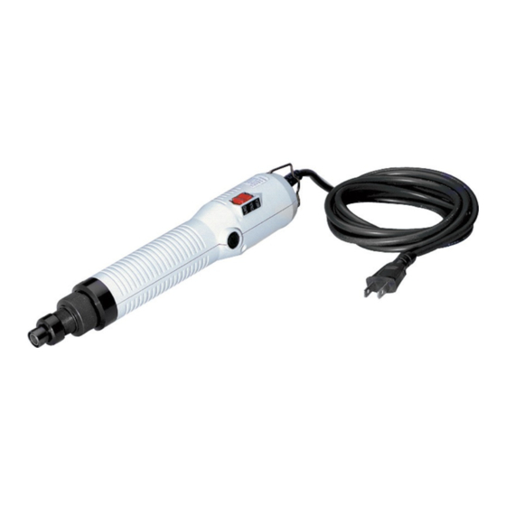
- Page 1 45527785 Edition 1 July 2008 Electric Screwdrivers ES 115V AC Series Maintenance Information Save These Instructions...
- Page 2 WARNING Always wear eye protection when operating or performing maintenance on this tool. Always turn off the air supply and disconnect the air supply hose before installing, removing or adjusting any accessory on this tool or before performing any maintenance on this tool. Note: (When reading the instructions, refer to exploded diagrams in parts Information Manuals when applicable (see under Related Documentation for form numbers).
- Page 3 7. Fit the two notches at the rear of the Gear Case Assembly (21 or For all other models, remove the Cam (25 or 27). Remove the 22) into an assembly fixture and using an open end wrench on Spindle Assembly (24 or 25), Gear Head Sun Gear (23 or 24) and the flats on the Clutch Housing Assembly (34 or 36), unscrew and Gear Head Assembly (22 or 23) from the Gear Case Assembly.
- Page 4 NOTICE Upper Motor Assembly Spring Spread the Ring only enough to remove it from the Bit Holder. Excessive expansion may damage the Ring. 12. Remove the Washer (32D or 33D), Slide Ring Spring (32C or 33C), Brush Cap Slide Ring Washer (32B or 33B) and Slide Ring (32A or 33A) from the Bit Holder.
- Page 5 Refer to Drawing TPD1053 on Page 3. Assembly, proceed as follows: NOTICE Apply 0.3 cc of Ingersoll Rand No. 67 Grease to the Spindle Assembly (24 or 25). Recalibrate the torque wrench every six months. Insert the Cam (25, 26A or 27), small end first, into the Gear Case (21 or 22).
-
Page 6: Troubleshooting Guide
Troubleshooting Guide Trouble Probable Cause Solution Starting microswitch is defective; replace the microswitch. Pilot Rod “H” is binding; clear obstruction or replace Rod. Does the microswitch “click” Pilot Rod “G” or Pilot Rod “ H is defective; repair or replace Rod. when the bit is pushed rearward Bit Holder is binding;... -
Page 7: Wiring Diagrams
Trouble Probable Cause Solution Does Bit speed exceed rated speed by Motor magnet is demagnetized; replace the motor. more than 100 rpm? Is Shut-off Brake microswitch functioning? (Does it click when button is depressed an Defective microswitch; replace the microswitch. does it test correctly with an ohmmeter?) Shut-off Brake Pilot Rods “H”, “G”... - Page 8 © 2008 Ingersoll Rand Company...
Need help?
Do you have a question about the ES 115V AC Series and is the answer not in the manual?
Questions and answers