
Subscribe to Our Youtube Channel
Related Manuals for Ingersoll-Rand EL 24V DC Series


Summary of Contents for Ingersoll-Rand EL 24V DC Series
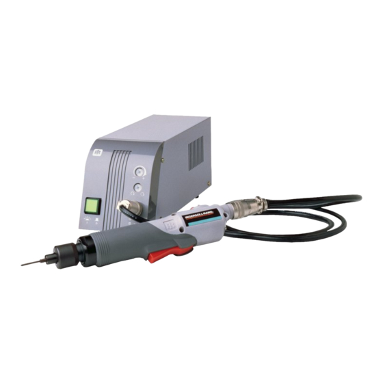
- Page 1 45530136 Edition 1 July 2008 Electric Screwdrivers EL 24V DC Series Maintenance Information Save These Instructions...
- Page 2 WARNING Always wear eye protection when operating or performing maintenance on this tool. Always turn off the air supply and disconnect the air supply hose before installing, removing or adjusting any accessory on this tool or before performing any maintenance on this tool. Note: When reading the instructions, refer to exploded diagrams in parts Information Manuals when applicable (see under Related Documentation for form numbers).
- Page 3 2. Using a thin slotted screwdriver, release the tension on the Brush 8. Remove the Push Rod (35 or 36) from the Armature. Spring (25 or 35) and remove the two Brush Assemblies (24 or 33) 9. Inspect the Push Rod. If it is worn, replace it. from the Rear End Plate (23 or 32).
- Page 4 16. Fit the two notches at the rear of the Gear Case Assembly into the 2. Apply grease to the end of the Plunger (13 or 37) and insert it Gear Case Fixture part no. EL0410B-J37. with the Plunger Spring (14 or 38) into the Switch Plate. 17.
-
Page 5: Troubleshooting Guide
TRANSFORMER VOLTAGE TRANSFORMER FORWARD/REVERSE SW YELLOW BLUE YELLOW MOTOR MOTOR VOLTAGE BLUE TRIGGER SW WHITE CONTROL BASE ASSEMBLY BLACK BRAKE SW SCREWDRIVER CONTROLLER (Dwg. TPD1817) Troubleshooting Guide Trouble Probable Cause Solution Defective Power Cord Assembly. Replace the Power Cord Assembly if necessary. Is there power to the tool? No power from the Controller. -
Page 6: Related Documents
Trouble Probable Cause Solution Motor magnet is demagnetized. Does the speed of the Bit exceed rated speed by more than 100 rpm? Replace the motor. Is Brake Switch functioning? (Does it click when button is depressed and does it test correctly Defective Brake Switch. - Page 7 Notes:...
- Page 8 www.irtools.com © 2008 Ingersoll Rand Company...
Need help?
Do you have a question about the EL 24V DC Series and is the answer not in the manual?
Questions and answers