Ingersoll-Rand 5 Series Operation And Maintenance Manual
Air screwdrivers
Hide thumbs
Also See for 5 Series:
- Product information (56 pages) ,
- Operation and maintenance manual (23 pages) ,
- Maintenance information (9 pages)
Table of Contents
Advertisement
Available languages
Available languages
OPERATION AND MAINTENANCE MANUAL FOR
TPD1374
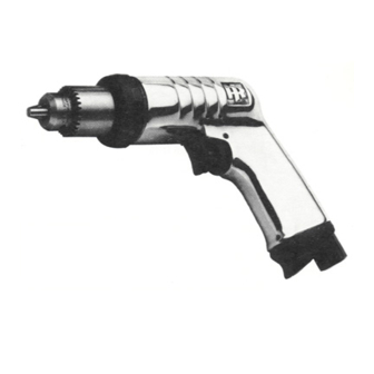
Series 5 Air Screwdrivers are designed for fastening applications in automotive and appliance
assembly, the electronic and aerospace industries and for woodworking and furniture
construction.
Ingersoll–Rand is not responsible for customer modification of tools for applications on which
Ingersoll–Rand was not consulted.
IT IS THE RESPONSIBILITY OF THE EMPLOYER TO PLACE THE INFORMATION
IN THIS MANUAL INTO THE HANDS OF THE OPERATOR.
FAILURE TO OBSERVE THE FOLLOWING WARNINGS COULD RESULT IN INJURY.
PLACING TOOL IN SERVICE
•
Always operate, inspect and maintain this tool in
accordance with American National Standards
Institute Safety Code for Portable Air Tools (ANSI
B186.1).
•
For safety, top performance, and maximum durability
of parts, operate this tool at 90 psig (6.2 bar/620 kPa)
maximum air pressure at the inlet with 1/4" (6 mm)
inside diameter air supply hose.
•
Always turn off the air supply and disconnect the air
supply hose before installing, removing or adjusting
any accessory on this tool, or before performing any
maintenance on this tool.
•
Do not use damaged, frayed or deteriorated air hoses
and fittings.
•
Be sure all hoses and fittings are the correct size and
are tightly secured. See Dwg. TPD905–1 for a typical
piping arrangement.
•
Always use clean, dry air at 90 psig maximum air
pressure. Dust, corrosive fumes and/or excessive
moisture can ruin the motor of an air tool.
•
Do not lubricate tools with flammable or volatile
liquids such as kerosene, diesel or jet fuel.
•
Do not remove any labels. Replace any damaged label.
USING THE TOOL
•
Always wear eye protection when operating or
performing maintenance on this tool.
The use of other than genuine Ingersoll–Rand replacement parts may result in safety hazards, decreased tool performance, and
increased maintenance, and may invalidate all warranties.
Repairs should be made only by authorized trained personnel. Consult your nearest Ingersoll–Rand Authorized Servicenter.
Refer All Communications to the Nearest
Ingersoll–Rand Office or Distributor.
Ingersoll–Rand Company 1999
Printed in U.S.A.
SERIES 5 AIR SCREWDRIVERS
IMPORTANT SAFETY INFORMATION ENCLOSED.
READ THIS MANUAL BEFORE OPERATING TOOL.
03528817
•
Always wear hearing protection when operating this
tool.
•
Keep hands, loose clothing and long hair away from
rotating end of tool.
•
Note the position of the reversing lever before
operating the tool so as to be aware of the direction of
rotation when operating the throttle.
•
Anticipate and be alert for sudden changes in motion
during start up and operation of any power tool.
•
Keep body stance balanced and firm. Do not
overreach when operating this tool. High reaction
torques can occur at or below the recommended air
pressure.
•
Tool accessories may continue to rotate briefly after
throttle is released.
•
Air powered tools can vibrate in use. Vibration,
repetitive motions or uncomfortable positions may be
harmful to your hands and arms. Stop using any tool
if discomfort, tingling feeling or pain occurs. Seek
medical advice before resuming use.
•
Use accessories recommended by Ingersoll–Rand.
•
The Throttle Valve Cap is under pressure from the
Throttle Valve Spring. Use care when removing the
Throttle Valve Cap. (On tools where applicable.)
•
This tool is not designed for working in explosive
atmospheres.
•
This tool is not insulated against electric shock.
F
Form P6411
Edition 14
E
September, 1999
P
Advertisement
Table of Contents

Subscribe to Our Youtube Channel
Related Manuals for Ingersoll-Rand 5 Series


Summary of Contents for Ingersoll-Rand 5 Series
- Page 1 03528817 Form P6411 Edition 14 September, 1999 OPERATION AND MAINTENANCE MANUAL FOR TPD1374 SERIES 5 AIR SCREWDRIVERS Series 5 Air Screwdrivers are designed for fastening applications in automotive and appliance assembly, the electronic and aerospace industries and for woodworking and furniture construction.
-
Page 2: Warning Label Identification
WARNING LABEL IDENTIFICATION FAILURE TO OBSERVE THE FOLLOWING WARNINGS COULD RESULT IN INJURY. WARNING WARNING WARNING Always turn off the air sup- Always wear eye protection Always wear hearing ply and disconnect the air when operating or perform- protection when operating supply hose before install- ing maintenance on this this tool. -
Page 3: Placing Tool In Service
PLACING TOOL IN SERVICE LUBRICATION the holder touches the Bit Holder Stop. Grasp the Front Clutch Jaw lightly in the vise and with the Allen wrench in the Bit Holder, index the Holder until the Clutch Spring Seat rises to permit easy lubrication of the Clutch Balls. Inject one stroke (0.3 cc) of I–R No. - Page 4 HOW TO ORDER A SCREWDRIVER REVERSIBLE PISTOL HANDLE with an ADJUSTABLE CUSHION CLUTCH Torque Range (Soft Draw) 90 psi Model in–lb 5RAKC1 14 – 25 1.6 – 2.8 5RALC1 13 – 35 1.5 – 4.0 5RALC3 13 – 35 1.5 – 4.0 5RANC1 13 –...
-
Page 5: Utilisation De L'outil
• • Utiliser les accessoires recommandés par Ne jamais lubrifier les outils avec des liquides Ingersoll-Rand. inflammables ou volatiles tels que le kérosène, le gasol • Le chapeau de la soupape de commande est soumis à ou le carburant d’aviation. - Page 6 SIGNIFICATION DES ETIQUETTES D’AVERTISSEMENT ATTENTION LE NON RESPECT DES AVERTISSEMENTS SUIVANTS PEUT CAUSER DES BLESSURES ATTENTION ATTENTION ATTENTION Couper toujours l’alimentation Porter toujours une Porter toujours des lunettes d’air comprimé et débrancher le protection acoustique de protection pendant flexible d’alimentation avant pendant l’utilisation de cet l’utilisation et l’entretien de d’installer, déposer ou ajuster...
-
Page 7: Mise En Service De L'outil
MISE EN SERVICE DE L’OUTIL LUBRIFICATION porte–embout. Serrer légèrement le crabot de limiteur avant dans un étau et, avec la clé Allen dans le porte–embout, indexer le porte–embout jusqu’à ce que le siège du ressort de limiteur se soulève pour permettre la lubrification des billes de limiteur. -
Page 8: Spécifications
SPÉCIFICATIONS Modèle Poignée Limiteur/ Gamme de couples Entraîneur recommandée pouces 5RAKC1 pistolet réversible amortisseur réglable 14–25 (1,6–2,8) 5RALC1 pistolet réversible amortisseur réglable 13–35 (1,5–4,0) 5RALC3 pistolet réversible amortisseur réglable 13–35 (1,5–4,0) 5RANC1 pistolet réversible amortisseur réglable 13–70 (1,5–8,0) 5RANC3 pistolet réversible amortisseur réglable 13–70 (1,5–8,0) 5RLLC1... -
Page 9: Uso De La Herramienta
MANUAL DE USO Y MANTENIMIENTO PARA TPD1374 ATORNILLADORES NEUMÁTICOS MODELO 5 NOTA Los Atornilladores Modelo 5 están diseñados para aplicaciones de montaje en la industria del automóvil y electrodomésticos, industrias electrónica y aeroespacial y para carpintería e industria del mueble. Ingersoll–Rand no aceptará... -
Page 10: Etiquetas De Aviso
ETIQUETAS DE AVISO AVISO EL HACER CASO OMISO DE LOS AVISOS SIGUIENTES PODRÍA OCASIONAR LESIONES. ADVERTENCIA ADVERTENCIA ADVERTENCIA Cortar siempre el suministro Use siempre protección ocular de aire y desconectar la man- Use siempre protección para guera de suministro de aire cuando utilice esta herramienta los oídos cuando utilice esta antes de instalar, retirar o ajus-... - Page 11 PARA PONER LA HERRAMIENTA EN SERVICIO LUBRICACIÓN Embrague Ajustable NOTA Gire la Tapa de Orificio de Ajuste hasta ver el orificio de ajuste. Sujete los lados planos de la Pieza Extrema en un Ingersoll–Rand Nº 10 Ingersoll–Rand Nº 28 tornillo de banco con cuidado para no dañar dichos lados Ingersoll–Rand Nº...
-
Page 12: Especificaciones
PARA PONER LA HERRAMIENTA EN SERVICIO ESPECIFICACIONES Modelo Empuñadura Embrague/ Gama de par Accionamiento recomendada in–lbs (Nm) 5RAKC1 pistola reversible amortiguación 14–25 (1,6–2,8) ajustable 5RALC1 pistola reversible amortiguación 13–35 (1,5–4,0) ajustable 5RALC3 pistola reversible amortiguación 13–35 (1,5–4,0) ajustable 5RANC1 pistola reversible amortiguación 13–70 (1,5–8,0) ajustable... - Page 13 MANUAL DE FUNCIONAMENTO E MANUTENÇÃO PARA APARAFUSADORAS PNEUMÁTICAS SÉRIE 5 TPD1383 AVISO As Aparafusadoras Pneumáticas Série 5 concebidas para aplicações de aperto em linhas de montagem, indústrias eletrónicas, aeroespaciais e de mobiliário. A Ingersoll–Rand não é responsável por modificações, feitas pelo cliente em ferramentas, nas quais a Ingersoll–Rand não tenha sido consultada.
- Page 14 IDENTIFICAÇÃO DO RÓTULO DE ADVERTÊNCIA ADVERTÊNCIA O NÃO CUMPRIMENTO DAS SEGUINTES ADVERTÊNCIAS PODE RESULTAR EM FERIMENTO. ADVERTÊNCIA ADVERTÊNCIA ADVERTÊNCIA Desligue sempre a alimentação de Use sempre óculos de pro- Use sempre protecção contra ar e desconecte a mangueira de tecção quando estiver ope– alimentação de ar antes de insta- o ruído ao operar esta ferra- rando ou executando algum...
- Page 15 COLOCANDO A FERRAMENTA EM FUNCIONAMENTO LUBRIFICAÇÃO extremidade aberta de 1” fixe as pás da Porca de Ajuste da Embraiagem. Insira uma chave Allen de 1/4” no Suporte do Bite e afrouxe até que suporte toque no Travão do Suporte do Bite. Agarre a Garra da Embraiagem Frontal levemente no torno e com uma Chave Allen no Suporte do Ingersoll–Rand No.
- Page 16 ESPECIFICAÇÕES Modelo Punho Embraiagem/Comando Intervalo de Toque Recomendado Nm (pés–lbs) 5RAKC1 pistola reversível mola ajustável 1,6–2,8 (14–25) 5RALC1 pistola reversível mola ajustável 1,5–4,0 (13–35) 5RALC3 pistola reversível mola ajustável 1,5–4,0 (13–35) 5RANC1 pistola reversível mola ajustável 1,5–8,0 (13–70) 5RANC3 pistola reversível mola ajustável 1,5–8,0 (13–70) 5RLLC1...
- Page 17 (Dwg. TPA807–5)
- Page 18 PART NUMBER FOR ORDERING PART NUMBER FOR ORDERING Motor Housing Assembly Inlet Bushing Assembly ....5RA–A565 • 19 L ratio Air Strainer Screen ....5RA–61 for 5RLL models ending Inlet Bushing Spacer .
-
Page 19: Maintenance Section
MAINTENANCE SECTION PART NUMBER FOR ORDERING Motor Housing Assembly K and L ratios for 5RAK and 5RAL models ending in C1, C3, D1 and P1 ..5RAK–A40 for 5RAK and 5RAL models ending in –EU ....5RAK–EU–A40 N ratio for 5RAN models ending in C1, C3, D1 or P1 . - Page 20 MAINTENANCE SECTION PART NUMBER FOR ORDERING PART NUMBER FOR ORDERING • 116 Gear Head Planet Gear 101 Rotor for K ratio (8 teeth) . . . 5RLK–53 for N ratio (3) for all others (6 teeth) . 5RLL–53 (13 teeth) ... 5RAN–9 102 Rear End Plate .
Need help?
Do you have a question about the 5 Series and is the answer not in the manual?
Questions and answers