Table of Contents
Advertisement
Advertisement
Table of Contents

Subscribe to Our Youtube Channel
Related Manuals for Progear Fitness 1113


Summary of Contents for Progear Fitness 1113
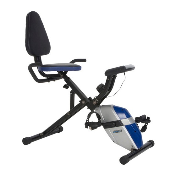
- Page 1 Foldable Semi-Recumbent Bike IMPORTANT: Read all instructions carefully before using this product. Retain this owner’s manual for future reference. The specifications of this product may vary from this photo, subject to change without notice. OWNER’S MANUAL Item #1113...
-
Page 2: Table Of Contents
TABLE OF CONTENTS SERVICE ------------------------------------------------------------------------ 2 LABEL PLACEMENT --------------------------------------------------------- 3 PRODUCT SAFETY ---------------------------------------------------------- 4 OVERVIEW DRAWING ------------------------------------------------------ 5 PARTS LIST --------------------------------------------------------------------- 6 HARDWARE LIST & TOOLS ----------------------------------------------- 8 ASSEMBLY --------------------------------------------------------------------- 9 COMPUTER --------------------------------------------------------------------- 15 ADJUSTMENTS ---------------------------------------------------------------- 17 STORAGE ----------------------------------------------------------------------- 18 TROUBLESHOOTING &... -
Page 3: Service
SERVICE IMPORTANT: FOR NORTH AMERICA ONLY To request product service and order replacement parts, please call our customer service department at: 1-866-924-1688 Monday through Friday, 8:00 AM-5:00 PM Pacific Standard Time, service@paradigmhw.com or email us at: Please visit our website at www.paradigmhw.com. Please have the following information ready when requesting for service: Your name Phone number... -
Page 4: Label Placement
LABEL PLACEMENT... -
Page 5: Product Safety
PRODUCT SAFETY Basic precautions should always be followed, including the following safety instructions when using this equipment. Read all instructions before using this equipment. Read all the instructions in this manual and do warm up exercises before using this equipment. Before exercising and to avoid injuring your muscles, perform warm-up exercise for each muscle group is highly recommended. -
Page 6: Overview Drawing
OVERVIEW DRAWING... -
Page 7: Parts List
PARTS LIST Description Qty No. Description 001 Rear Frame 1 025 France Nut 3/8" 002 Front Frame 1 026 Crank Cover Round Phillips Head Tapping 003 Rear Stabilizer Ø50 1 027 Screw ST4.2x20 004 Computer Frame 1 028 Big Curve Washer Ø8xØ25x1.5 005 Seat Post 1 029 Hexagon Cap Nut M8 006 Seat Cushion... - Page 8 PARTS LIST Description Qty No. Description 053 Nut M10x1.5xδ6.5 1 074 Back Cushion 054 Big Washer Ø10 1 075 Handlebar Ø25x1.5t 055 Wave Washer Ø17.5xØ23xδ0.3 1 076 Back Cushion Frame 056 Idle Wheel Axle Ø17x37 1 077 Square End Cap (30x30) 057 Nylon Nut M10 1 078 Carriage Bolt M8x50 058 Bearing 6202...
-
Page 9: Hardware List & Tools
HARDWARE LIST & TOOLS (78) Carriage Bolt (62) Big Washer M8x50 Ø8xØ25x1.5 2 PCS 2 PCS (81) Spring Washer Ø8 4 PCS (80) Hexagon Socket Bolt M8x45 4 PCS (28) Big Curve Washer Ø8xØ25x1.5 6 PCS (79) Hexagon Socket (32) Hexagon Socket Bolt M8x40 Bolt M6x12 2 PCS... -
Page 10: Assembly
ASSEMBLY Tool: Double Open End Wrench 13#, 15# 1. Front and Rear Stabilizers Installation Remove the Ø10x110 Safety Pin (38) from the bike. Pull the Rear and Front Frames (1, 2) apart from each other. Align pin holes for inserting the Ø10x110 Safety Pin (38) then insert the removed Ø10x110 Safety Pin (38) into the holes on the Rear and Front Frames (1, 2) to lock the frames in place. - Page 11 ASSEMBLY Hardware: (28) Big Curve Washer Ø8xØ25x1.5 (29) Hexagon Nut Cap M8 4 PCS 4 PCS ․․․․․․․․․․․․․․․․․․․․․․․․․․․․․․․․․․․․․․ Important: Important: Please make sure the right foot Screw Right Foot Pedal (7R) pedal matches up with the right into right crank clockwise! crank and the left foot pedal Screw Left Foot Pedal (7L) matches up with the left crank.
- Page 12 ASSEMBLY Tool: Allen Wrench with Phillips Screwdriver 5# 3. Seat Cushion and Seat Post Installation Remove four M8x15 Hexagon Socket Bolts (60) and four Ø8 Spring Washers (81) from underside of the Seat Cushion (6). Remove bolts with the Allen Wrench with Phillips Screwdriver provided.
- Page 13 ASSEMBLY Tool: Double Open End Wrench 13#, 15# Allen Wrench with Phillips Screwdriver 5# 4. Back Cushion Frame and Back Cushion Installation Attach the Back Cushion Frame (76) onto the Seat Post (5) with two M8 Nylon Nuts (34), two Ø8xØ25x1.5 Big Washers (62), and two M8x50 Carriage Bolts (78). Tighten nylon nuts with the Double Open End Wrench provided.
- Page 14 ASSEMBLY Tool: Allen Wrench with Phillips Screwdriver 5# 5. Handlebar Installation Attach the Handlebar (75) onto the Back Cushion Frame (76) with two Ø8xØ25x1.5 Big Curve Washers (28) and two M8x40 Hexagon Socket Bolts (79). Tighten bolts with the Allen Wrench with Phillips Screwdriver provided. Hardware: (28) Big Curve Washer Ø8xØ25x1.5 (79) Hexagon Socket Bolt M8x40...
- Page 15 ASSEMBLY Tool: Allen Wrench with Phillips Screwdriver 5# 6. Computer Installation Connect the Extension Hand Pulse Sensor Wires III (89) from the Handlebar (75) to the Extension Hand Pulse Sensor Wires II (90) from the Seat Post (5). Install the Computer Bracket (10) to the Computer Post (4) by sliding the Computer Bracket (10) into the Computer Frame (4), using four M6x12 Hexagon Socket Bolts (32) and four Ø6 Spring Washers (35).
-
Page 16: Computer
COMPUTER SPECIFICATIONS: TIME ---------------------------------------------- 0:00-99:59 MIN: SEC SPEED ------------------------------------------- 0.0-999.9 MPH DIST (DISTANCE) ----------------------------- 0.00-99.99 MILE CAL (CALORIES) ------------------------------ 0.0-999.9 KCAL ODO (ODOMETER) -------------------------- 0.00-99.99 MILE PULSE ------------------------------------------- 40-200 BEATS/MIN USING YOUR COMPUTER The computer can be activated by pressing the button or by pedaling. If you leave the equipment idle for 4 minutes, the power will turn off automatically. - Page 17 COMPUTER HOW TO INSTALL THE BATTERIES: Remove the battery cover on the back of the computer. Place two "SIZE-AAA" batteries into the battery housing. Insure batteries are correctly positioned and battery springs are proper contact with batteries. Re-install the battery cover. If the display is illegible or only partial segment appears, remove the batteries and wait 15 seconds before reinstalling.
-
Page 18: Adjustments
ADJUSTMENTS Adjusting the Tension Control Knob To increase the tension, turn the tension control knob in a clockwise direction. To decrease the tension, turn the tension control knob in a counterclockwise direction. Tension Control Knob Adjusting the Seat Height Turn the seat height adjustment knob in a counterclockwise direction until the seat post can be slid up or down and then slide the seat post up or down direction to the... -
Page 19: Storage
STORAGE (87) Back Cushion Tube (2) Front Frame (4) Computer Post (22) Safety Pin Ø8x110 (92) Safety Pin (22) Safety Pin Ø8x110 Ø8x65 (38) Safety Pin Ø10x110 (1) Rear Frame (92) Safety Pin (38) Safety Pin Ø8x65 Ø10x110 For your convenience, the bike can be folded up and placed in a storage area. Remove the Ø8x65 Safety Pin (92) from the bike. -
Page 20: Troubleshooting & Maintenance
TROUBLESHOOTING & MAINTENANCE TROUBLESHOOTING PROBLEM: There is no display on the computer console. SOLUTION: Verify the sensor wire that comes from the computer post is properly plugged into the SENSOR receptacle located on the back of the computer. SOLUTION: Check if the batteries are correctly positioned and battery springs are in proper contact with batteries. -
Page 21: Warm Up
WARM UP Quadriceps Stretch With one hand against a wall for balance, reach behind you and pull your right foot up. Bring your heel as close to your buttocks as possible. Hold for 15 counts and repeat with left foot up. Inner Thigh Stretch Sit with the soles of your feet together with your knees pointing outward. -
Page 22: Warranty
WARRANTY Paradigm Health & Wellness, Inc. warrants to the original purchaser that this product is free from defects in material and workmanship when used for the purpose intended, under the conditions that it has been installed and operated in according to Paradigm Health & Wellness, Inc.’s Owner’s Manual. Paradigm Health &... -
Page 23: Fax Form
FAX FORM Paradigm Health & Wellness, Inc. PARTS REQUEST FAX FORM Please fax this form to (1-626-810-2166) OR YOU CAN EMAIL CUSTOMER SERVICE REQUESTS TO service@paradigmhw.com NAME: _______________________________________________________ ADDRESS: ____________________________________________________ CITY ______________ STATE ______________ ZIP ___________________ TELEPHONE: (Day) _____________________________________________ (Night) ____________________________________________ (Email Address) ____________________________________ SERIAL#: __________________________________________ MODEL#: __________________________________________...
Need help?
Do you have a question about the 1113 and is the answer not in the manual?
Questions and answers
What does scan mean on fitness bike
The SCAN function on the Progear Fitness bike model 1113 automatically cycles through each display function (such as time, speed, distance, calories, odometer, and pulse) in sequence, changing every 6 seconds.
This answer is automatically generated