Table of Contents

Related Manuals for Progear Fitness 1202


Summary of Contents for Progear Fitness 1202
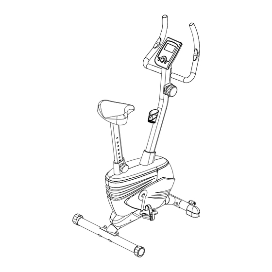
- Page 1 Upright Bike IMPORTANT: Read all instructions carefully before using this product. Retain this owner’s manual for future reference. The specifications of this product may vary from this photo, subject to change without notice. OWNER’S MANUAL Item #1202...
-
Page 2: Table Of Contents
TABLE OF CONTENTS SERVICE ------------------------------------------------------------------------ 2 LABEL PLACEMENT --------------------------------------------------------- 3 PRODUCT SAFETY ---------------------------------------------------------- 4 OVERVIEW DRAWING ------------------------------------------------------ 5 PARTS LIST --------------------------------------------------------------------- 6 HARDWARE LIST & TOOLS ----------------------------------------------- 8 ASSEMBLY ---------------------------------------------------------------------- 9 COMPUTER --------------------------------------------------------------------- 14 ADJUSTMENTS --------------------------------------------------------------- 17 TROUBLE SHOOTING & MAINTENANCE ----------------------------- 18 WARM UP ---------------------------------------------------------------------- 19 WARRANTY -------------------------------------------------------------------- 20 FAX FORM ---------------------------------------------------------------------- 21... -
Page 3: Service
SERVICE IMPORTANT: FOR NORTH AMERICA ONLY To request product service and order replacement parts, please call our customer service department at: 1-866-924-1688 Monday through Friday, 8:00 AM-5:00 PM Pacific Standard Time, service@paradigmhw.com or email us at: Please visit our website at www.paradigmhw.com. Please have the following information ready when requesting for service: Your name Phone number... -
Page 4: Label Placement
LABEL PLACEMENT... -
Page 5: Product Safety
PRODUCT SAFETY Basic precautions should always be followed, including the following safety instructions when using this equipment. Read all instructions before using this equipment. Read all the instructions in this manual and do warm up exercises before using this equipment. Before exercise, in order to avoid injuring the muscle, warm-up exercise of every position of the body is necessary. -
Page 6: Overview Drawing
OVERVIEW DRAWING... -
Page 7: Parts List
PARTS LIST Description Qty No. Description 001 Main Frame Ø50x1.5t 1 028 Front Stabilizer End Cap Ø50 002 Handlebar Ø25x1.5t 1 029 Rear Stabilizer End Cap Ø50 003 Handlebar Post 70x30x1.5t 1 030 Cover Cap 004 Rear Stabilizer Ø50x1.5x15 inches 1 031 Handlebar Post Cover 005 Flywheel Ø230 1 032... - Page 8 PARTS LIST Description Qty No. Description 055 Washer Ø12xØ6x1.5t 1 061 Transport Wheel Ø23xØ6x32 056 Washer Ø10.2xØ14x1t 2 062 Bolt M6x1.9 inches 057 Bolt M5x20 1 063 Nylon Nut M6 058 Bolt M8x12 1 064 Bottle Holder 059 Eyebolt M6x36 2 065 Bolt M8x0.6 inches 060 Tension Bracket...
-
Page 9: Hardware List & Tools
HARDWARE LIST & TOOLS (#34) Cap Nut (#35) Carriage Bolt (#36) Big Curve Washer 4 PCS 4 PCS 4 PCS Allen Wrench with Phillips Screwdriver Multi Hex Tool 1 PC 1 PC... -
Page 10: Assembly
ASSEMBLY Important: Screw Right Pedal (#21) into right crank clockwise! Screw Left Pedal (#20) into Left crank counter-clockwise! Important: Please make sure the right pedal matches up with the right crank and the left pedal matches up with the left crank. If reversed the cranks may become damaged or stripped. - Page 11 ASSEMBLY Tool: Multi Hex Tool 2. Seat Post, Seat Post Cover, and Seat Cushion Installation Remove three Washers (#38) and three Nylon Nuts (#42) from underside of the Seat Cushion (#27). Remove nylon nuts and washers with the Multi Hex Tool provided. Guide bolts on underside of the Seat Cushion (#27) through holes on top of the Seat Post (#25), attach with three removed Washers (#38) and Nylon Nuts (#42).
-
Page 12: Tension Control Knob 1
ASSEMBLY Tool: Allen Wrench with Phillips Screwdriver 3. Handlebar Post, Handlebar Post Cover, and Tension Control Knob Installation Remove five Bolts (#24), four Washers (#38), and one Curve Washer (#37) from the tube of the Main Frame (#1). Remove bolts with the Allen Wrench with Phillips Screwdriver provided. - Page 13 ASSEMBLY Tool: Allen Wrench with Phillips Screwdriver 4. Handlebar and Computer Installation Remove two Bolts (#65) and two Curve Washers (#37) from the Handlebar Post (#3). Remove bolts with the Allen Wrench with Phillips Screwdriver provided. Insert the Hand Pulse Sensor Wires (#53) into the hole on the Handlebar Post (#3) and then pull them out from the top end of the Handlebar Post (#3).
- Page 14 ASSEMBLY Tool: Allen Wrench with Phillips Screwdriver 5. Bottle Holder Installation Remove two Bolts (#47) from the Handlebar Post (#3). Remove bolts with the Allen Wrench with Phillips Screwdriver provided. Attach the Bottle Holder (#64) onto the Handlebar Post (#3) with two Bolts (#47). Tighten bolts with the Allen Wrench with Phillips Screwdriver provided.
-
Page 15: Computer
COMPUTER SPECIFICATIONS: TMR (TIMER) ----------------------------- 0:00-99:59 MIN: SEC SPD (SPEED) ---------------------------- 0.0-999.9 MPH DIS (DISTANCE) ------------------------- 0.0-999.9 MILES CAL (CALORIES) ------------------------ 0.0-999.9 KCAL ODO (ODOMETER) -------------------- 0-9999 MILES RPM ----------------------------------------- 0-9999 REVOLUTIONS/MIN P (PULSE) -------------------------------- 40-239 BEATS/MIN ACTIVATING THE COMPUTER The computer can be activated by pressing the buttons or by pedaling. - Page 16 COMPUTER SPEED: Display the current speed. DIS (DISTANCE): Displays the accumulative distance traveled during workout. You may also pre-set target distance in STOP mode before training. To set DIS (DISTANCE) press the MODE button until you see the DIS on the screen. Press the SET button until DIS start blinking then press the SET button to change the distance, each time you press the SET button, the value will increase by 1.0 mi.
- Page 17 COMPUTER HOW TO INSTALL THE BATTERIES: Remove the battery cover on the back of the computer. Place two "SIZE-AA" batteries into the battery housing. Insure batteries are correctly positioned and battery springs are proper contact with batteries. Re-install the battery cover. If the display is illegible or only partial segment appear, remove batteries and wait 15 seconds before reinstalling.
-
Page 18: Adjustments
ADJUSTMENTS Adjusting the Tension Control Knob To increase the tension, turn the tension control knob in a clockwise direction. To decrease the tension, turn the tension control knob in a counterclockwise direction. Tension Control Knob Adjusting the Rear Stabilizer End Cap Turn the rear stabilizer end cap on the rear stabilizer as needed to level the upright bike. -
Page 19: Trouble Shooting & Maintenance
TROUBLE SHOOTING & MAINTENCE TROUBLE SHOOTING PROBLEM: The upright bike wobbles when in use. SOLUTION: Turn the rear stabilizer end cap on the rear stabilizer as needed to level the upright bike. PROBLEM: There is no display on the computer console. SOLUTION: Remove the computer console and verify the wires that come from the computer console are properly connected to the wires that come from the handlebar post. -
Page 20: Warm Up
WARM UP Quadriceps Stretch With one hand against a wall for balance, reach behind you and pull your right foot up. Bring your heel as close to your buttocks as possible. Hold for 15 counts and repeat with left foot up. Inner Thigh Stretch Sit with the soles of your feet together with your knees pointing outward. -
Page 21: Warranty
WARRANTY Paradigm Health & Wellness, Inc. warrants to the original purchaser that this product is free from defects in material and workmanship when used for the purpose intended, under the conditions that it has been installed and operated in according to Paradigm Health & Wellness, Inc.’s Owner’s Manual. Paradigm Health &... -
Page 22: Fax Form
FAX FORM Paradigm Health & Wellness, Inc. PARTS REQUEST FAX FORM Please fax this form to (1-626-810-2166) OR YOU CAN EMAIL CUSTOMER SERVICE REQUESTS TO service@paradigmhw.com NAME: _______________________________________________________ ADDRESS: ____________________________________________________ CITY ______________ STATE ______________ ZIP ___________________ TELEPHONE: (Day) _____________________________________________ (Night) ____________________________________________ (Email Address) ____________________________________ SERIAL#: __________________________________________ MODEL#: __________________________________________...
Need help?
Do you have a question about the 1202 and is the answer not in the manual?
Questions and answers