Table of Contents
Advertisement
Quick Links
Advertisement
Table of Contents

Subscribe to Our Youtube Channel
Related Manuals for Progear Fitness 1310


Summary of Contents for Progear Fitness 1310
- Page 1 INDOOR TRAINING BIKE OWNER’S MANUAL Item #1310...
-
Page 2: Table Of Contents
TABLE OF CONTENTS SERVICE ------------------------------------------------------------------------- 2 WARNING LABEL PLACEMENT ------------------------------------------ 3 PRODUCT SAFETY ----------------------------------------------------------- 4 OVERVIEW DRAWING -------------------------------------------------------5 PART LIST ----------------------------------------------------------------------- 6 INCLUDED HARDWARE & TOOLS --------------------------------------- 8 ASSEMBLY ---------------------------------------------------------------------- 9 COMPUTER --------------------------------------------------------------------- 17 ADJUSTMENTS ---------------------------------------------------------------- 19 MAINTENANCE & TROUBLE SHOOTING ----------------------------- 20 WARM UP ----------------------------------------------------------------------- 21 WARRANTY -------------------------------------------------------------------- 22 FAX FORM ---------------------------------------------------------------------- 23... -
Page 3: Service
SERVICE IMPORTANT: FOR NORTH AMERICA ONLY To request product service and order replacement parts, please call our customer service department at: 1-866-924-1688 Monday through Friday, 8:00 AM-5:00 PM Pacific Standard Time, service@paradigmhw.com or email us at: Please visit our website at www.paradigmhw.com. Please have the following information ready when requesting for service: Your name Phone number... -
Page 4: Warning Label Placement
WARNING LABEL PLACEMENT... -
Page 5: Product Safety
PRODUCT SAFETY Basic precautions should always be followed, including the following safety instructions when using this equipment: Read all instructions before using this equipment. 1. Read all the instructions in this manual and do warm up exercises before using this equipment. 2. -
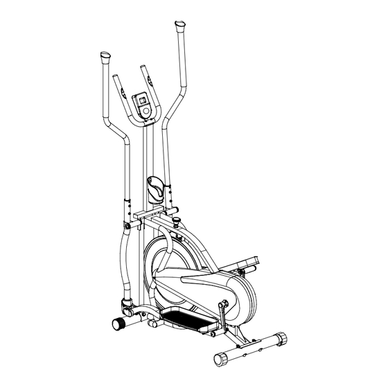
Page 6: Overview Drawing
OVERVIEW DRAWING... -
Page 7: Part List
PART LIST Description Qty No. Description 001 Handrail Arm End Cap Ø25 2 023 Right Bolt for Right Crank Ø16x119 1 1 024 Wave Washer Ø16.2xØ26xδ0.3 002 Right Handrail Arm Ø25x2 Handrail Arm Foam Grip 2 025 Right Foot Bar Ø23xØ32x220 Handrail Arm Plastic Bushing 2 026 Spring Washer 1/2"... - Page 8 PART LIST Description Qty No. Description 046 Spring Washer Ø8 6 073 Sensor with Wire L=900 mm 047 Bearing 6000ZZ 2 074 Chain Pulley 048 Flywheel Ø448 1 075 Left Crank 7", 1/2" 049 Flywheel Axle Ø10x149 1 076 Left Cover 696x282x92.4 050 Spacer Ø14xØ10.2x25.5 1 077 Left Handrail 051 Bolt M8x60...
-
Page 9: Included Hardware & Tools
INCLUDED HARDWARE & TOOLS... -
Page 10: Assembly
ASSEMBLY Tool: Multi Hex Tool 13#, 17#, 19# 1. Front and Rear Stabilizers Installation Position the Front Stabilizer (52) in front of Main Frame (68) and align bolt holes. Attach the Front Stabilizer (52) onto the front curve of the Main Frame (68) with two M8x60 Bolts (51), two Ø8.4xØ20x16 Big Curve Washers (54), and two M8 Cap Nuts (55). - Page 11 ASSEMBLY Tool: Allen Wrench 6# Allen Wrench with Phillips Screwdriver 6# Multi Hex Tool 13#, 17#, 19# Allen Wrench 8# 2. Left/Right Handrails and Left/Right Foot Bars Installation Place the Ø15.8x373 Rotation Rod (37) into the hole on the Main Frame (68). Slide the Right/Left Handrails (9, 77) onto the Ø15.8x373 Rotation Rod (37) and secure in place with two 3/8"x20 Bolts (5), two 3/8"...
- Page 12 ASSEMBLY Please note: Before you put the 1/2” Nylon Nut for Right Crank (27) and a 1/2" Spring Washer (26) on the Right Foot Bar (25), make sure the Ø16x119 Right Bolt for Right Crank (23) had been screwed to the end position with the Right Foot Bar (25). (79) LEFT (23) RIGHT In order to install the hinge bolt properly, keep it...
- Page 13 ASSEMBLY Hardware: (23) Right Bolt for Right Crank Ø16x119 1 PC (24) Wave Washer Ø16.2xØ26xδ0.3 2 PCS (26) 1/2" Spring Washer 2 PCS (27) 1/2” Nylon Nut for Right Crank 1 PC (79) Left Bolt for Left Crank Ø16x119 1 PC (98) 1/2”...
- Page 14 ASSEMBLY Tool: Allen Wrench 6# 3. Hand Pulse Handlebar Support Frame, Bottle Holder, and Hand Pulse Handlebar Installation Attach the Hand Pulse Handlebar Support Frame (40) onto the Main Frame (68) with four M8x35 Bolts (36). Tighten bolts with the 6# Allen Wrench provided. Connect the Sensor Wire (73) from the Main Frame (68) to the Extension Sensor Wire (38) from the Hand Pulse Handlebar Support Frame (40), see Figure A.
- Page 15 ASSEMBLY Tool: Multi Hex Tool 13#, 17#, 19# Allen Wrench 6# 4. Right and Left Foot Pedals Installation Attach two Foot Pedal Support Brackets (80) onto both Right/Left Foot Bars (25, 78) with four M8x43 Bolts (17), four Ø8.5xØ16x1.5 Washers (19), and four M8 Nylon Nuts (18).
- Page 16 ASSEMBLY Tool: Allen Wrench 6# 5. Right/Left Handrail Arms and Computer Installation Insert the Right Handrail Arm (2) into the handrail arm plastic bushing on the tube of the Right Handrail (9) and secure with two M8x35 Bolts (36) and Ø8 Spring Washers (46).
-
Page 17: Computer
COMPUTER SPECIFICATIONS: TIME ---------------------------------------------- 00:00-99:59 MIN: SEC SPEED ------------------------------------------- 0.0-99.9 MPH DISTANCE -------------------------------------- 0.00-99.99 MILE CALORIES -------------------------------------- 0-9999 CAL PULSE ------------------------------------------- 40-240 BPM USING YOUR COMPUTER The computer can be activated by pressing the MODE button or by pedaling. If you leave the equipment for 4 minutes, the power will shut off automatically. BUTTON FUNCTIONS: Press the MODE button to select each function of the computer. - Page 18 COMPUTER HOW TO INSTALL THE BATTERIES: Remove the battery cover on the back of the computer. Place two "SIZE-AA" batteries into the battery housing. Insure batteries are correctly positioned and battery springs are in proper contact with batteries. Re-install the battery cover. If the display is illegible or only partial segment appear, remove batteries and wait 15 seconds before reinstalling.
-
Page 19: Adjustments
ADJUSTMENTS Adjusting the Tension Control Knob To increase the tension, turn the tension control knob in a clockwise direction. Tension Control Knob To decrease the tension, turn the tension control knob in a counterclockwise direction. Adjusting the Rear Stabilizer End Cap Turn the rear stabilizer end cap on the rear stabilizer as needed to level the training bike. -
Page 20: Maintenance & Trouble Shooting
MAINTENCE & TROUBLE SHOOTING MAINTENANCE Cleaning The training bike can be cleaned with a soft cloth and any mild detergent. Do not use abrasives or solvents on plastic parts. Please wipe your perspiration off the training bike after each use. Be careful not get excessive moisture on the computer display panel as this might cause an electrical hazard or electronics to fail. -
Page 21: Warm Up
WARM UP Quadriceps Stretch With one hand against a wall for balance, reach behind you and pull your right foot up. Bring your heel as close to your buttocks as possible. Hold for 15 counts and repeat with left foot up. Inner Thigh Stretch Sit with the soles of your feet together with your knees pointing outward. -
Page 22: Warranty
WARRANTY Paradigm Health & Wellness, Inc. warrants to the original purchaser that this product is free from defects in material and workmanship when used for the purpose intended, under the conditions that it has been installed and operated in according to Paradigm Health & Wellness, Inc.’s Owner’s Manual. Paradigm Health &... -
Page 23: Fax Form
FAX FORM Paradigm Health & Wellness, Inc. PARTS REQUEST FAX FORM Please fax this form to (1-626-810-2166) OR YOU CAN EMAIL CUSTOMER SERVICE REQUESTS TO service@paradigmhw.com NAME: _______________________________________________________ ADDRESS: ____________________________________________________ CITY ______________ STATE ______________ ZIP ___________________ TELEPHONE: (Day) _____________________________________________ (Night) ____________________________________________ (Email Address) ____________________________________ SERIAL#: __________________________________________ MODEL#: __________________________________________...
Need help?
Do you have a question about the 1310 and is the answer not in the manual?
Questions and answers