Table of Contents
Advertisement
Quick Links
Advertisement
Table of Contents

Subscribe to Our Youtube Channel
Related Manuals for Progear Fitness 1211


Summary of Contents for Progear Fitness 1211
- Page 1 INDOOR TRAINING BIKE OWNER’S Item #1211 MANUAL...
-
Page 2: Table Of Contents
TABLE OF CONTENTS SERVICE ------------------------------------------------------------------------ 2 WARNING LABEL PLACEMENT ------------------------------------------ 3 PRODUCT SAFETY ---------------------------------------------------------- 4 OVERVIEW DRAWING ------------------------------------------------------- 5 PART LIST ----------------------------------------------------------------------- 6 HARDWARE & TOOLS PACK --------------------------------------------- 8 ASSEMBLY --------------------------------------------------------------------- 9 COMPUTER --------------------------------------------------------------------- 13 ADJUSTMENTS ---------------------------------------------------------------- 14 MOVING THE BIKE ----------------------------------------------------------- 16 TROUBLESHOOTING &... -
Page 3: Service
SERVICE IMPORTANT: FOR NORTH AMERICA ONLY To request product service and order replacement parts, please call our customer service department at: 1-866-924-1688 Monday through Friday, 8:00 AM-5:00 PM Pacific Standard Time, service@paradigmhw.com or email us at: Please visit our website at www.paradigmhw.com. Please have the following information ready when requesting for service: Your name Phone number... -
Page 4: Warning Label Placement
WARNING LABEL PLACEMENT... -
Page 5: Product Safety
PRODUCT SAFETY Basic precautions should always be followed, including the following safety instructions when using this equipment. Read all instructions before using this equipment. 1. Read all the instructions in this manual and do warm up exercises before using this equipment. 2. -
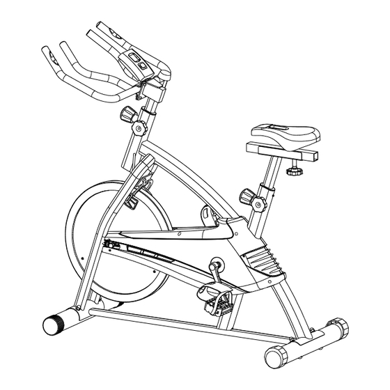
Page 6: Overview Drawing
OVERVIEW DRAWING... -
Page 7: Part List
PART LIST Description Qty No. Description 001 Cap Nut M10x1 2 028 Bearing Nut II 15/16" 002 Eyebolt M6 2 029 Bearing 003 Spring Washer Ø6 2 030 Bearing Cup 004 Spring Washer Ø10 2 031 Round Knob M16 005 Hexagon Flange Nut M6 3 032 Plastic Bushing 006 Screw ST4.2x17 6 033 Handlebar Post... - Page 8 PART LIST Description Qty No. Description Handlebar Foam Grip 056 Sensor with Wire L=1000 mm 1 072 Ø33xØ23x450 Phillips Pan Head Self Drilling 9 073 Hand Pulse Sensor Screw ST4.2x19 Handlebar Foam Grip 058 Screw ST4.2x19 7 074 Ø33xØ23x340 059 Brake Pad 80x39x9 2 075 Screw ST3.5x8 060 Brake Bracket 2 076 Small Magnet Ø15x7...
-
Page 9: Hardware & Tools Pack
HARDWARE & TOOLS PACK (16) Bolt M8x70 4 PCS (19) Curve Washer Ø8 4 PCS (20) Cap Nut M8 4 PCS (80) Bolt M5x10 2 PCS STEP 2 (34) Bolt M8x15 4 PCS (35) Spring Washer Ø8 4 PCS (36) Washer Ø8 4 PCS STEP 1 STEP 3... -
Page 10: Assembly
ASSEMBLY Hardware (STEP 1): (16) Bolt M8x70 4 PCS (19) Curve Washer Ø8 4 PCS (20) Cap Nut M8 4 PCS Tool: Double Open End Wrench #13, #15 1. Front and Rear Stabilizers Installation Position the Front Stabilizer (17) in front of the Main Frame (21) and align bolt holes. Attach the Front Stabilizer (17) onto the front curve of the Main Frame (21) with two M8x70 Bolts (16), two Ø8 Curve Washers (19), and two M8 Cap Nuts (20). - Page 11 ASSEMBLY Important: Important: Please make sure the right foot Screw Right Foot Pedal pedal matches up with the right (24R) into right crank crank and the left foot pedal clockwise! matches up with the left crank. Screw Left Foot Pedal (24L) If reversed the cranks may into Left crank become damaged or stripped.
- Page 12 ASSEMBLY Turn the Round Knob (31) on the Main Frame (21) in a counterclockwise direction until it can be pulled out. Pull out the Round Knob (31) and then slide the Seat Post (41) up or down direction to the suitable position. Lock the Seat Post (41) in place by releasing the Round Knob (31) and sliding the Seat Post (41) up or down slightly until the Round Knob (31) "pops"...
- Page 13 ASSEMBLY Tool: Allen Wrench with Phillips Screwdriver #6 3. Hand Pulse Handlebar, Dial Tension Control Knob, and Computer Installation Attach the Hand Pulse Handlebar (37) with Computer Bracket (40) onto the Handlebar Post (33) with four M8x15 Bolts (34), four Ø8 Spring Washers (35), and four Ø8 Washers (36).
-
Page 14: Computer
COMPUTER USING YOUR COMPUTER The computer can be activated by pressing the button or by pedaling. If you leave the computer idle for 4 minutes, the power will shut off automatically. BUTTON FUNCTIONS: MODE: Press the MODE button to select each function of the computer. Press and hold the MODE button for 4 seconds to reset all data values to zero. -
Page 15: Adjustments
ADJUSTMENTS HOW TO INSTALL THE BATTERIES: Remove the battery cover on the back of the computer. Place two "SIZE-AA" batteries into the battery housing. Insure batteries are correctly positioned and battery springs are in proper contact with batteries. Re-install the battery cover. If the display is illegible or only partial segment appears, remove the batteries and wait 15 seconds before reinstalling. - Page 16 ADJUSTMENTS Round Knob Lock Knob Adjusting the Seat Height Loosen the Lock Knob and then loosen the Round Knob by turning counterclockwise direction until it can be pulled out. Pull out the Round Knob and then slide the Seat Post up or down direction to the suitable position. Lock the Seat Post in place by releasing the Round Knob and sliding the Seat Post up or down slightly until the Round Knob "pops"...
-
Page 17: Moving The Bike
MOVING THE BIKE Start by carefully pushing down on the handlebar until the rear end of the bike lifts in the air. Carefully push the bike to the desired location. -
Page 18: Troubleshooting & Maintenance
TROUBLESHOOTING & MAINTENCE TROUBLESHOOTING PROBLEM: The training bike wobbles when in use. SOLUTION: Turn the rear stabilizer on the rear stabilizer as needed to level the training bike. PROBLEM: There is no display on the computer console. SOLUTION: Verify the wire that comes from the computer console is properly connected to the wire that comes from the computer. -
Page 19: Warm Up
WARM UP Quadriceps Stretch With one hand against a wall for balance, reach behind you and pull your right foot up. Bring your heel as close to your buttocks as possible. Hold for 15 counts and repeat with left foot up. Inner Thigh Stretch Sit with the soles of your feet together with your knees pointing outward. -
Page 20: Warranty
WARRANTY Paradigm Health & Wellness, Inc. warrants to the original purchaser that this product is free from defects in material and workmanship when used for the purpose intended, under the conditions that it has been installed and operated in according to Paradigm Health & Wellness, Inc.’s Owner’s Manual. Paradigm Health &... -
Page 21: Fax Form
FAX FORM Paradigm Health & Wellness, Inc. PARTS REQUEST FAX FORM Please fax this form to (1-626-810-2166) OR YOU CAN EMAIL CUSTOMER SERVICE REQUESTS TO service@paradigmhw.com NAME: _______________________________________________________ ADDRESS: ____________________________________________________ CITY ______________ STATE ______________ ZIP ___________________ TELEPHONE: (Day) _____________________________________________ (Night) ____________________________________________ (Email Address) ____________________________________ SERIAL#: __________________________________________ MODEL#: __________________________________________...
Need help?
Do you have a question about the 1211 and is the answer not in the manual?
Questions and answers