Table of Contents
Advertisement
Advertisement
Table of Contents

Subscribe to Our Youtube Channel
Related Manuals for Progear Fitness 555LXT


Summary of Contents for Progear Fitness 555LXT
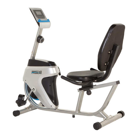
- Page 1 Progear 555LXT Magnetic Tension Recumbent Bike IMPORTANT: Read all instructions carefully before using this product. Retain this owner’s manual for future reference. The specifications of this product may vary from this photo, subject to change without notice. 3151.3-101216...
-
Page 3: Table Of Contents
TABLE OF CONTENT SERVICE ------------------------------------------------------------------------ 2 LABEL PLACEMENT --------------------------------------------------------- 3 PRODUCT SAFETY ---------------------------------------------------------- 4 OVERVIEW DRAWING ------------------------------------------------------ 5 HARDWARE & TOOLS PACK ---------------------------------------------- 6 PART LIST ----------------------------------------------------------------------- 7 ASSEMBLY ---------------------------------------------------------------------- 9 CONSOLE ---------------------------------------------------------------------- 15 ADJUSTMENTS --------------------------------------------------------------- 16 TROUBLE SHOOTING & MAINTENANCE ----------------------------- 17 WARRANTY -------------------------------------------------------------------- 18 PARTS REQUEST FORM---------------------------------------------------- 19... -
Page 4: Service
SERVICE IMPORTANT: FOR NORTH AMERICA ONLY For damaged, defective products, questions, replacement parts, or any other service support, please contact our customer service department (8:00 AM - 5:00 PM Pacific Standard Time, Daily) by the below methods: For Best Service, please Email: Service@paradigmhw.com Response Time: 1-2 Business Days Website:... -
Page 5: Label Placement
LABEL PLACEMENT... -
Page 6: Product Safety
PRODUCT SAFETY Basic precautions should always be followed when using this equipment. Read all instructions before using this equipment which include the following safety instructions: Read all the instructions in this manual and do warm up exercises before using this equipment. Before exercising, and in order to avoid injuring your muscles, it is recommended that you perform warm-up exercises for every muscle group. -
Page 7: Overview Drawing
OVERVIEW DRAWING... -
Page 8: Hardware & Tools Pack
HARDWARE & TOOLS LIST... -
Page 9: Part List
PART LIST Description Description Hex Nut 7/8” Main Frame Flat Washer Ф23*Ф34.5*δ2.5 Front Post Bearing Nut 7/8” Front Stabilizer Idler Arm Ball Bearing Left Handlebar Bearing Cup Right Handlebar Sensor Inductor Cross Recess Head Tapping Seat Post Screw ST2.9*12 Bearing Nut 15/16” Rear Stabilizer Flat Washer Ф24*Ф40*δ3.0 Clip... - Page 10 PART LIST Description Description 55 Cross Recess Head Screw M6*15 Adjustable Leveler 56 Backrest Rear Stabilizer End Cap 57 Square End Cap Sensor Wire 58 Round Cap Left Pedal Strap 59 Handrail Foam Grip Right Pedal Strap Spring Washer Ф8 60 Hex Bolt M8*58 Spring Washer Ф5 61 Nylon Nut M8...
-
Page 11: Assembly
ASSEMBLY NO. 78 Open-Ended Flat Wrench S10, S13, S17, S19 1PC 1.1 Front Stabilizer Installation A. Lift up the front of the Main Frame (1), and attach the Front Stabilizer (3) onto the front curve of the Main Frame (1) with two Carriage Bolts (19), two Big Curve Washers (20), two Spring Washers (74), and two Cap Nuts (21). - Page 12 ASSEMBLY The Cranks, Pedal Straps, Pedal Shafts, and Foot Pedals are marked “R” for Right and “L” for Left. NO.77 Multi Hex Tool S10, S13, S14, S15 1PC 2.1 Pedal Strap installation A. Install the Left Pedal Strap (70) onto the Left Pedal (24). Install the Right Pedal Strap (71) onto the Right Pedal (41).
- Page 13 ASSEMBLY 3.1 Seat Post Installation A. Attach the Seat Post (7) and the Seat Bracket (63), onto the Main Frame (1) with one Washer (64), one Wave Washer (75), and Round Knob (65). B. Secure the Seat Post (7) by tightening the Round Knob (65) in a clockwise direction. NO.
- Page 14 ASSEMBLY NO.77 Multi Hex Tool S10, S13, S14, S15 1PC 4.1 Backrest Installation Remove the four Screws (55), four Spring Washers (45) and the four Flat Washers (54) from the Backrest (56). Align the holes of the Backrest (56) to the holes of Seat Post (7).
- Page 15 ASSEMBLY NO. 76 Allen Wrench 6mm 1PC 5. Front Post Installation A. Remove four Hex Bolts (16), four Spring Washers (72), two Flat Washers (17) and two Curved Washers (18) from the Main Frame (1). B. Connect the Sensor Inductor (33) and Sensor Wire (69); See Figure A. C.
- Page 16 ASSEMBLY NO.77 Multi Hex Tool S10, S13, S14, S15 1PC 6.1 Tension Knob Installation A. Remove the Screw (12), the Spring Washer (73), and the Flat Washer (13) from the Tension Knob (14). B. Hook the cable of the Tension Knob (14) into the Tension Cable (15); See Figure A. C.
-
Page 17: Console
CONSOLE Display Information: TIME----------------------------------------------------- 00:00-99:59 SPEED ------------------------------------------------- 0.0-99.9 ML/H DISTANCE (DIST) ----------------------------------- 0.00-9999 ML CALORIES (CAL) ------------------------------------ 0.0-9999 CAL ODOMETER (ODO) --------------------------------- 0.0-9999 ML BUTTON FUNCTIONS: ON/OFF (START/STOP): The console will turn on when any button is pressed or when you start pedaling. -
Page 18: Adjustments
ADJUSTMENTS Rear Stabilizer (8) Adjustable Leveler (67) Rear Stabilizer End Cap (68) Adjusting the Rear Stabilizer End Cap Adjust the Rear Stabilizer End Caps (68) on the Rear Stabilizer (8) as needed to level the recumbent bike. Adjust the Adjustable Leveler If the bike is bouncing when in use, turn the Adjustable Leveler (67) so that is making contact with the floor. -
Page 19: Trouble Shooting & Maintenance
TROUBLE SHOOTING & MAINTENANCE TROUBLE SHOOTING PROBLEM: The recumbent bike wobbles when in use. 1)SOLUTION: Turn the Rear Stabilizer End Caps (68) on the Rear Stabilizer (8) or Adjustable Leveler (67) on the bottom of the rear Main Frame (1) as needed to level the recumbent bike. -
Page 20: Warranty
WARRANTY MANUFACTURER’S LIMITED WARRANTY Paradigm Health & Wellness warrants to the original purchaser that this product is free from defects in material and workmanship when used for the purpose intended, under the conditions that it has been installed and operated in accordance with Paradigm’s Owner’s Manual. -
Page 21: Parts Request Form
PARTS REQUEST FORM Paradigm Health & Wellness, Inc. EMAIL THIS FORM WITH YOUR RECIEPT OF PURCHASE TO Service@paradigmhw.com NAME: _______________________________________________________ ADDRESS: ____________________________________________________ CITY ______________ STATE ______________ ZIP ___________________ TELEPHONE: (Day) _____________________________________________ (Night) ____________________________________________ SERIAL#: _____________________________________________________ MODEL#: _____________________________________________________ PURCHASE DATE: ______________________________________________ PLACE OF PURCHASE: _________________________________________ PART # DESCRIPTION...
Need help?
Do you have a question about the 555LXT and is the answer not in the manual?
Questions and answers