
Related Manuals for Aaeon Gene-4310


Summary of Contents for Aaeon Gene-4310
- Page 1 Gene-4310 All-in-One 3.5" Single Board Cyrix GXLV computer with LCD, Ethernet, Audio & 2 COMs...
-
Page 2: Fcc Statement
FCC STATEMENT THIS DEVICE COMPLIES WITH PART 15 FCC RULES. OPERATION IS SUBJECT TO THE FOLLOWING TWO CONDITIONS: (1) THIS DEVICE MAY NOT CAUSE HARM- FUL INTERFERENCE. (2) THIS DEVICE MUST ACCEPT ANY INTERFERENCE RECEIVED INCLUDING INTERFERENCE THAT MAY CAUSE UNDESIRED OPERATION. THIS EQUIPMENT HAS BEEN TESTED AND FOUND TO COMPLY WITH THE LIMITS FOR A CLASS "A"... -
Page 3: Copyright Notice
SiS is a trademark of Silicon Integrated Systems Corp. VIA is a trademark of VIA Technology, Inc. All other product names or trademarks are properties of their respective owners. Part No. 2047431000 Manual Gene-4310 1st Edition Prepared in Taiwan July 2000... -
Page 4: Technical Support
Our dealers are well trained and ready to give you the support you need to get the most from your AAEON products. In fact, most problems reported are minor and are able to be easily solved over the phone. -
Page 5: Product Warranty
Because of AAEON’s high quality-control standards and rigorous testing, most of our customers never need to use our repair service. If an AAEON product is defective, it will be repaired or replaced at no charge during the warranty period. For out-of-warranty repairs, you will be billed according to the cost of replacement materials, service time, and freight. -
Page 6: Packing List
Before you begin installing your card, please make sure that the following materials have been shipped: • 1 GENE-4310 All-in-One Single Board Computer • 1 Hard disk drive (IDE) interface cable (44 pin, pitch 2.0mm) • 1 Floppy disk drive interface (34 pin, ptich 2.0mm) •... - Page 7 Notice Dear Customer, Thank you for purchasing the GENE-4310 board. This user’s manual is designed to help you to get the most out of the GENE- 4310, please read it thoroughly before you install and use the board. The product that you have purchased comes with an two- year limited warranty, but AAEON will not be responsible for misuse of the product.
-
Page 8: Table Of Contents
Contents Chapter 1: General Information.......1 Introduction ..............2 Features .................. 3 Specifications ................. 4 Board layout ................7 Board dimensions ..............9 Chapter 2: Installaion ........11 Jumpers and connectors ............ 12 Locating jumpers & connector ......... 14 Setting jumpers ..............16 Installing DRAM (DIMMs) .......... - Page 9 Display connectors (J14, J16) ........... 30 100Base-T Ethernet connector (CN2) ......32 Power connector (P1) ............32 Keyboard and PS/2 mouse connector (CN11) ....33 Chapter 3: Award BIOS Setup ......35 Starting setup ............... 36 Setup keys ................37 Getting help .................
-
Page 11: Chapter 1: General Information
General Information This chapter gives background informa- tion on the mainboard. Sections include: • Board specifications • Layout and dimensions Chapter 1 General Information... -
Page 12: Introduction
3D audio and up to 1024 x 768 resolution @ 64K colors with UMA 4MB SDRAM display memory. Major onboard devices adopt PCI technology to achieve outstanding computing performance when used with NS GXLV level processors, making the GENE-4310 one of the world's smallest and most powerful all-in-one multimedia boards. -
Page 13: Features
Features • 3.5" FDD SubCompact Form Factor • Supports NS Geode GXLV Low-power BGA CPUs • Supports CRT and 18-bit TFT Panels • LVDS interface • 10/100Base-T Fast Ethernet • Integrated AC-97 2.0 SoundBlaster compatible Audio • Supports Compact Flash Storages •... -
Page 14: Specifications
Battery: Lithium battery for data retention Watchdog Timer:Can generate a system reset or IRQ15. Supports Win98, Win3.1. Software selectable time-out interval (15 sec. ~ 3825sec., 15 sec./ step) DMA: 7 DMA channels (8237 equivalent) Interrupt: 15 interrupt levels (8259 equivalent) Gene-4310 User Manual... - Page 15 Power management: I/O peripheral devices support power saving and doze/standby/suspend modes. APM 1.2 compliant H/W status monitoring: Winbond W83781D H/W status monitoring IC supportspower supply voltages, fan speed, and temperatures monitoring Flat Panel/CRT Interface • Chipset: NS CS5530 • Display memory: Shared UMA up to 4MB •...
- Page 16 Power connectors: 4-pin HDD type Mechanical and Environmental Power supply voltage: +5V (4.75V to 5.25V) Operating temperature: 32 to 140 F (0 to 60 Board size: 5.75" (L) x 4" (W) (146 mm x 101.6 mm) Weight: 0.88 lb. (0.4 Kg) Gene-4310 User Manual...
-
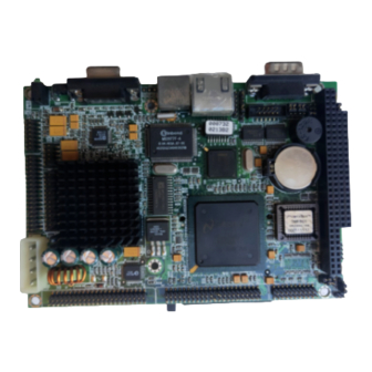
Page 17: Board Layout
Board layout Chapter 1 General Information... - Page 18 Board layout Gene-4310 User Manual...
-
Page 19: Board Dimensions
Board dimensions Chapter 1 General Information... - Page 20 Board dimensions Gene-4310 User Manual...
-
Page 21: Chapter 2: Installaion
Installation This chapter describes how to set up the main board hardware, including instruc- tions on setting jumpers and connecting peripherals, switches, and indicators. Be sure to read all the safety precautions before you begin the installation proce- dure. Chapter 2 Installation 11... -
Page 22: Jumpers And Connectors
Onboard buzzer and external speaker select COM2 RS232/422/485 select JP12 COM2 RS232/422/485 select JP8 (1-3-5) LCD Panel voltage select JP8 (2-4-6) Backlight voltage select JP11 Watchdog Timer output select JP13 LVDS Edge Trigger select (4310S only) 12 Gene-4310 User Manual... - Page 23 Connectors Label Function SO-DIMM 144 Pin socket IDE connector (2.0 mm) Compact Flash Disk socket COM1 D-SUB 9 Pin connector COM2 RS232/422/485 connector (2.0 mm) Dual USB connector (2.0 mm) PS/2 Mouse and Keyboard connector FDD connector (2.0 mm) LPT1 Parallel Port connector (2.0 mm) Reset Switch connector LCD connector (2.0 mm) LVDS interface connector (2.0 mm)
-
Page 24: Locating Jumpers & Connector
Locating jumpers & connectors JP13 CN1/PC104 JP1 JP8 JP11 JP10 JP12 Jumper Pin Number JP12 JP13 JP11 14 Gene-4310 User Manual... - Page 25 Locating jumper & connectors Chapter 2 Installation 15...
-
Page 26: Setting Jumpers
A pair of needle-nose pliers may be helpful when working with jumpers. If you have any doubts about the best hardware configuration for your application, contact your local distributor or sales representa- tive before you make any changes. 16 Gene-4310 User Manual... -
Page 27: Installing Dram (Dimms)
Installing SDRAM (SODIMM) System Memory The reverse side of the Gene-4310 contains a socket for 144-pin dual inline memory module (SODIMM). The socket uses 3.3 V unbuffered synchronous SDRAM and is available in capacities of 16, 32, 64, or 128 MB. The socket can be filled in the SODIMM of any size, giving your GENE-4310 single board computer between 16 and 128 MB of memory. -
Page 28: Clear Cmos (Jp2 1~3)
1-2 closed. Clear CMOS (JP2 1~3) Protect* Clear CMOS *default Onboard buzzer / external speaker select JP2 (4~7) Onboard buzzer / external speaker select JP2 (4~7) Internal buzzer* External speaker * default 18 Gene-4310 User Manual... -
Page 29: Irda Connector (Jp3)
IrDA connector (JP3) The IrDA connector (JP3) can be configured to support wireless infrared module, with this module and application software such as laplink or Win95 Direct Cable connection, user can transfer files to or from laptops, notebooks, PDA and printers. This connector supports HPSIR (115.2Kbps, 2 meters), ASK-IR (56Kbps) and Fast IR (4Mbps, 2 meters). -
Page 30: Com2 Rs-232/422/485 Select (Jp12, Jp4)
COM2 RS-232/422/485 select (JP12, JP4) The Gene-4310 COM2 serial port can be selected as RS-232, RS-422, or RS-485 by setting JP12 and JP4. COM2 Select (JP12, JP4) RS-232* RS-422 RS-485 1 4 7 10 1 4 7 10 1 4 7 10... -
Page 31: Lcd Driving Voltage Select (Jp8 1-3-5)
LCD driving voltage select (JP8 1-3-5) You can select the LCD connector J14 (pin 5 and pin 6) driving voltage by setting JP8 1-3-5. The configurations are as follows: LCD driving voltage select (JP8 1-3-5) 3.3V * *default LCD backlight voltage select & output (JP8 2-4-6) (JP10) You can set the JP10 for LCD backlight voltage to 5V or 12V output, by configuring JP8 2-4-6. -
Page 32: Watchdog Timer Output Select (Jp11)
Watchdog timer output select (JP11) Watchdog timer output select (JP11) IRQ15 Reset * JP11 *default LVDS edge trigger select (JP13) (4310T only) LVDS edge trigger select (JP13) Falling edge * Rising edge JP13 *default 22 Gene-4310 User Manual... -
Page 33: Ide Hard Drive Connector (J2)
IDE hard drive connector (J2) You can attach one or two Enhanced Integrated Device Electronics hard disk drives to the mainboard's internal controller. The mainboard's IDE controller uses a PCI local-bus interface. This advanced interface supports faster data transfer and allows the IDE hard drive to exceed 528 MB. -
Page 34: Ide Hard Drive Connector (J2)
DATA 0 DATA 15 SIGNAL GND DREQ IO WRITE IO READ IO CHANNEL READY 28 DACK# IRQ14 IOCS16 ADDR 1 ADDR 0 ADDR 2 HARD DISK SELECT 0 HARD DISK SELECT 1 IDE ACTIVE MGND MVCC 24 Gene-4310 User Manual... -
Page 35: Serial Ports (J4, J5)
Serial ports (J4, J5) The Gene-4310 offers two serial ports, one RS-232 and one RS-232/ 422/485. These ports allow you to connect them to serial devices (mouse, printers, etc.). COM 2 RS-232/422/485 serial ports (J5) COM1, COM2, RS-232/422/485 serial port... -
Page 36: Usb Connector (J7)
USB connector (J7) The Gene-4310 provides two USB (Universal Serial Bus) interfaces, which give complete plug and play, hot attach/detach for up to 127 external devices. The USB interfaces comply with USB specifica- tion Rev. 1.0, and can be disabled in the system BIOS setup. -
Page 37: Floppy Drive Connector (J9)
Floppy drive connector (J9) You can attach up to two floppy drives to the mainboard control- ler. You can use any combination of 5¼" (360 KB and 1.2 MB) and/or 3½" (720 KB, 1.44 MB, and 2.88 MB) drives. A 34-pin daisy-chain drive connector cable is required for a dual- drive system. -
Page 38: Floppy Drive Connector (J9)
Floppy drive connector (J9) Signal Signal DENSITY SELECT DRIVE TYPE INDEX MOTOR 0 DRIVE SELECT 1 DRIVE SELECT 2 MOTOR 1 DIRECTION STEP WRITE DATA WRITE GATE TRACK 0 WRITE PROTECT READ DATA HEAD DELECT DISK CHANGE 28 Gene-4310 User Manual... -
Page 39: Parallel Port Connector (J10)
DB-25 connector on the other. Parallel port IRQ The Gene-4310 supports one parallel port. The port is designated as LPT1 and can be disabled or changed to LPT2 or LPT3 in the system BIOS setup. -
Page 40: Display Connectors (J14, J16)
Signal Signal Red video DENSITY SELECT (no pin) Green video Sync return (GND) Blue video Monitor ID (not used) Not used Monitor ID Horizontal Sync Red returned(GND) Vertical Sync Green returned(GND) Not used Blue returned (GND) 30 Gene-4310 User Manual... - Page 41 LCD connector (J14) J14 is a 44-pin, dual-in-line header used for flat panel displays. When the mainboard's power is applied, the control signal is low until just after the relevant flat panel signals are present. Configuration of the VGA interface is done completely via the software utility.
-
Page 42: 100Base-T Ethernet Connector (Cn2)
Power connector (P1) In single board computer (non-passive backplane) applications, you will need to connect the power to the Gene-4310 board using P1. This connector is fully compatible with the standard PC power supply connector. See the following table for its pin assignments:... -
Page 43: Keyboard And Ps/2 Mouse Connector (Cn11)
Keyboard and PS/2 mouse connector (CN11) The Gene-4310 provides a keyboard connector which supports both a keyboard and a PS/2 style mouse. In most cases, especially in embedded applications, a keyboard is not used. The standard PC/AT BIOS will report an error or fail during power-on-self-test (POST) after a reset if the keyboard is not present. - Page 44 34 Gene-4310 User Manual...
-
Page 45: Chapter 3: Award Bios Setup
Award BIOS Setup This chapter describes how to configure the BIOS for the Gene-4310. Chapter 3 Award BIOS Setup... -
Page 46: Starting Setup
Ctr-Alt-Del. If you do not press the keys at the correct time and the system does not boot, an error message appears and you are again asked to PRESS F1 TO CONTINUE, DEL TO ENTER SETUP Gene-4310 User Manual... -
Page 47: Setup Keys
Setup keys These keys helps you navigate in Setup: Up arrow Move to previous item Down arrow Move to next item Left arrow Move to the item in the left hand Right arrow Move to the item in the right hand Main Menu: Quit and not save changes into CMOS RAM Other pages: Exit current page and return to... -
Page 48: Getting Help
The Chipset defaults have been carefully chosen by Award Software or your system manufacturer for the best performance and reliability. Even a seemingly small change to the Chipset setup may causing the system to become unstable. Gene-4310 User Manual... -
Page 49: Main Setup Menu
Main setup Menu Standard CMOS Options in the original PC AT-compatible BIOS. BIOS Features Award Software enhanced BIOS options. Chipset Features Options specific to your system chipset. Power Advanced Power Management (APM) Management options. PnP/PCI Plug and Play standard and PCI Local Bus Configuration configuration options. - Page 50 Load Setup Setup defaults are factory settings for Defaults optimal-performance system operations. Save & Exit Save settings in nonvolatile CMOS Setup RAM and exit Setup. Exit Without Abandon all changes and exit Setup. Save Gene-4310 User Manual...
-
Page 51: Standard Cmos Setup
Standard CMOS setup When you choose the STANDARD CMOS SETUP option from the INITIAL SETUP SCREEN menu, the screen below is displayed. Chapter 3 Award BIOS Setup... - Page 52 The BIOS can automatically detect the specifications and optimal operating mode of almost all IDE hard drives. When you select type AUTO for a hard drive, the BIOS detects its specifications during POST, every time the system boots. Gene-4310 User Manual...
- Page 53 If you do not want to select drive type AUTO, other methods of selecting the drive type are available: 1.Match the specifications of your installed IDE hard drive(s) with the preprogrammed values for drive types 1 through 45. 2.Select USER and enter values into each drive parameter field. 3.Use the IDE HDD AUTO DECTECTION function in Setup.
- Page 54 5-1/4 inch AT-type high-density drive; 1.2 megabyte capacity 720K, 3.5 in 3-1/2 inch double-sided drive; 720 kilobyte capacity 1.44M, 3.5 in 3-1/2 inch double-sided drive; 1.44 mega byte capacity 2.88M, 3.5 in 3-1/2 inch double-sided drive; 2.88 mega byte capacity Gene-4310 User Manual...
- Page 55 Halt On During the power-on-self-test (POST), the computer stops if the BIOS detects a hardware error. You can tell the BIOS to ignore certain errors during POST and continue the boot-up process. These are the selections: • No errors: POST does not stop for any errors. •...
-
Page 56: Bios Features Setup
BIOS features setup By choosing the BIOS FEATURES SETUP option from the INITIAL SETUP SCREEN menu, the screen below is displayed. Gene-4310 User Manual... - Page 57 The displayed configuration is based on the manufacturer's SETUP DEFAULTS settings. Virus Warning When enabled, you receive a warning message if a program (specifically, a virus) attempts to write to the boot sector or the partition table of the hard disk drive. You should then run an anti- virus program.
- Page 58 Gate A20. Setting Gate A20 to Fast improves system speed, particularly with OS/2 and Windows. Security Option If you have set a password, select whether the password is required every time the System boots, or only when you enter Setup. Gene-4310 User Manual...
- Page 59 Shadow Software that resides in a read-only memory (ROM) chip on a device is called firmware. The AwardBIOS permits shadowing of firmware such as the system BIOS, video BIOS, and similar operat- ing instructions that come with some expansion peripherals, such as, for example, a SCSI adaptor.
-
Page 60: Chipset Features Setup
CHIPSET features setup By choosing the CHIPSET FEATURES SETUP option from the INITIAL SETUP SCREEN menu, the screen below is displayed. Gene-4310 User Manual... - Page 61 These two fields let you add recovery time (in bus clock cycles) for 16-bit and 8-bit I/O. USB Controller The Gene-4310 supports 2 sets of USB for connection. To Enable the onboard USB controller please set to Enable, otherwise set to Disable as default.
- Page 62 PS/ 2 KB or PS/2 Mouse by their USB equivalents. Hardware monitoring support The Gene-4310 support onboard monitoring as CPU temperature, Fan speed, and Voltages for user reference. Gene-4310 User Manual...
-
Page 63: Power Management Setup
Power management setup By choosing the POWER MANAGEMENT option from the INITIAL SETUP SCREEN menu, the screen below is displayed. Chapter 3 Award BIOS Setup... - Page 64 After the selected period of drive inactivity, any system IDE devices compatible with the ATA-2 specification or later power manage themselves, putting themselves into an idle state after the specified timeout and then waking themselves up when accessed. Gene-4310 User Manual...
- Page 65 MODEM Use IRQ Name the interrupt request (IRQ) line assigned to the modem (if any) on your system. Activity of the selected IRQ always awakens the system. Throttle Duty Cycle When the system enters Doze mode, the CPU clock runs only part of the time.
-
Page 66: Pnp/Pci Configuration Setup
PNP/PCI configuration setup By choosing the PNP/PCI CONFIGURATION SETUP option from the initial SETUP SCREEN menu, the screen below is displayed. Gene-4310 User Manual... - Page 67 PNP OS Installed Select Yes if the system operating environment is Plug-and-Play aware (e.g., Windows 95). Resources Controlled By The Plug and Play AwardBIOS can automatically configure all the boot and Plug and Play-compatible devices. If you select Auto, all the interrupt request (IRQ) and DMA assignment fields disappear, as the BIOS automatically assigns them.
-
Page 68: Load Bios Defaults/Load Setup Defaults
LOAD SETUP DEFAULTS, on the other hand, provides for maximum system performance. If the stored record created by the setup utility becomes corrupted (and therefore unusable), BIOS defaults will load automatically when you turn the Gene-4310 on. Gene-4310 User Manual... -
Page 69: Integrated Peripherals Setup
Integrated peripherals setup By choosing the INTEGRATD PERIPHERALS option from the initial SETUP SCREEN menu, the screen below is displayed. Chapter 3 Award BIOS Setup... - Page 70 IDE device. KBC input clock The Gene-4310 offer four kind of frequency for user option, as default 6MHz, 8 MHz, 12 MHz, and 16 MHz. RING POWER ON Controller Onboard FDC Controller Select Enabled if your system has a floppy disk controller (FDC) installed on the system board and you wish to use it.
- Page 71 ECP Mode Use DMA Select a DMA channel for the port. Onboard IR controller Enable or Disable the onboard IR controller, as default is Disable. When you set it to Enable. There are several item will be appear as below. IR Address select: Set IR address as (2F8H, 3E8H, 2E8H, 3E0H, 2E0H, 3F8H) IR Mode: Setup IR mode as (IrDA, ASKIR, FIR, CIR)
- Page 72 Video Memory size Share memory from DIMM, from 1.5MB to 4MB. TV output Mode The Gene-4310 onboard support TV output function for option. (NTSC, PAL). Panel Clock Freg There are 4 kind of LCD frequency for option as 60MHz , 72 MHz, 80 MHz, and 85 MHz.
-
Page 73: Supervisor/User Password Setting
Supervisor/User password setting You can set either SUPERVISOR or USER PASSWORD, or both of them. The difference between the two is that the supervisor password allows unrestricted access to enter and change the options of the setup menus, while the user password only allows entry to the program, but not modify options. - Page 74 System Enter a password each time the system boots and when ever you enter Setup. Setup Enter a password when ever you enter Setup. NOTE: To clear the password, simply press Enter when asked to enter a password. Then the password function is disabled. Gene-4310 User Manual...
-
Page 75: Ide Hdd Auto Detection
IDE HDD auto detection The IDE HDD AUTO DETECTION utility can automatically detect the IDE hard disk installed in your system. You can use it to self- detect and/or correct the hard disk type configuration. You need to repeat the setup for each of the IDE combinations: Chapter 3 Award BIOS Setup... -
Page 76: Save & Exit Setup
CMOS memory. The microprocessor will check this every time you turn your system on and compare this to what it finds as it checks the system. This record is required for the system to operate. Gene-4310 User Manual... -
Page 77: Exit Without Saving
Exit without saving If you select this option and press <ENTER>, the values entered in the setup utility will be recorded in the chipset's CMOS memory. The microprocessor will check this every time you turn your system on and compare this to what it finds as it checks the system. - Page 78 Ethernet Software Configuration This chapter describes how to configure the Etherent Card to match your applica- tion requirements. Chapter 4 Software Configuration...
-
Page 79: Chapter 3: Ethernet Software Configuration
The Ethernet Setup Menu also offers three very useful diagnos- tic functions. These are: 1. Run EEPROM test 2. Run Diagnostics on Board 3. Run Diagnostics on Network Each option has its own display screen which shows the format and result of any diagnostic tests undertaken. Gene-4310 User Manual... -
Page 80: Watchdog Timer
Programming the Watchdog Timer The mainboard is equipped with a watchdog timer that resets the CPU or generates an interrupt if processing comes to a standstill for whatever reason. This feature ensures system reliability in industrial stand-alone and unmanned environments. Appendix A Programming the Watchdog Timer... -
Page 81: Appendix A: Programming The Watchdog Timer
Configuration register The watchdog timer of Gene-4310 is located on the chipset – Winbond W83977. If you want to use it, you have to know how to read/write the configuration register of W83977. The basic proce- dure is as follows. -
Page 82: Programming The Watchdog Timer
How to set the watchdog timer 1.Set register 30h of logical device 7 to 1 to activate the timer. 2.Write the desired counter value to register F2h of logical deivice Logical Device 7 : Register number 30h (CR30) 00h : Logical device is inactive 01h : Activates the logical device Logicel Device 8 : Register number F2h (CRF2) 00h : Time-out Disable... - Page 83 ;; write 01h to register 30h to activate ;; timer call W977Write ;; mov bl,8 ;; Select logical device number 8 ax,01f2h ;; write time-out value (01h) to register ;; F2h call W977Write ;; set time-out value to 32 sec ah,4ch SetWatchDog_Time ENDP Gene-4310 User Manual...
- Page 84 ;; Enter to I/O Chip Program Configuration Register Mode Enterv Config proc push push al,87h ;; Specific value to enter Config ;; Mode dx,cs:CONFIG_PORT dx,al ;; Write to Config Port twice! dx,al ;; Delay EnterConfig endp ;; Exit to I/O Chip Program Configuration Register Mode ExitConfig proc push ax push dx...
- Page 85 ;; Write to Config Port al,bl ;; Write logical device number dx,cs:DATA_PORT ;; to Data Port dx,al SelectDevice endp ;; Setting I/O Chip Program Configuration Register Value ;; Input : al = register number ;; ah = setting value Gene-4310 User Manual...
- Page 86 W977Write PROC push call EnterConfig ;; Enter Config Mode call SelectDevice ;; Select logical device dx,cs:CONFIG_PORT dx,al ;; Select register number al,ah dx,cs:DATA_PORT dx,al call ExitConfig ;; Exit Config Mode W977Write ENDP Appendix A Programming the Watchdog Timer...
- Page 87 Gene-4310 User Manual...
Need help?
Do you have a question about the Gene-4310 and is the answer not in the manual?
Questions and answers