
Subscribe to Our Youtube Channel
Related Manuals for Nanoptix PayCheck Slim


Summary of Contents for Nanoptix PayCheck Slim
-
Page 1: Service Manual
Service Manual First Edition December 11, 2009 August 29, 2011 Document # 720006-0000... -
Page 2: Legal Notices
Legal Notices Disclaimer Information in this document is subject to change without notice. Consult your Nanoptix Inc. sales representative for information that is applicable and current. Nanoptix Inc. reserves the right to improve products as new technology, components, software and firmware become available. - Page 3 AC line filtering, over-current and short-circuit protection. Use of this product with a power supply other than the Nanoptix Inc. power supply will require you to test the power supply and Nanoptix Inc. printer for FCC and CE mark certification.
-
Page 4: Table Of Contents
4 Mechanical Drawings ....................20 5 Spare parts replacement instructions ..............25 6 Printer Maintenance Instructions ................32 7 Service & Support ....................37 Returning printers back to Nanoptix for repairs (RMA)........37 Technical Support Contact Information..............37 Document # 720006-0000 August, 2011... - Page 5 Service Manual Figures 1: N .......... 1 IGURE ANOPTIX HECK RINTER 2: T ............3 IGURE ICKET TACK RIENTATION 3: P ..............4 IGURE APER UTTON 4: P ................. 5 IGURE RINTER ESET 5: I ..............7 IGURE NTERFACE ORTS 6: LED P .................
- Page 6 Service Manual Tables 1: S ................2 ABLE PECIFICATIONS 2: I ............... 7 ABLE NTERFACE ORTS 3: LED I ..............8 ABLE NFORMATION 4: RS232 )......... 12 ABLE RECEPTACLE NTERFACE FEMALE 5: 14-P RS-232 U ......12 ABLE NIVERSAL NTERFACE 6: P ) ....
-
Page 7: About The Printer
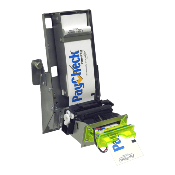
About the Printer 1.1 Description of Printer The Nanoptix PayCheck Slim printer, is extremely fast, quiet, and very reliable. With thermal printing technology, there is no ribbon cassette to change, and paper loading is extremely simple. The printer’s intuitive design enables it to fit in very narrow cabinets. -
Page 8: General Specifications
Service Manual 1.2 General specifications Direct Thermal Print Method 8 dot/mm (203 dpi) Resolution Print Width 64mm 65mm Paper Width Cartridge Size Operating Temperature 0° to 50° C -20° to 60° C Storage Temperature 5 to 90% RH at 50°C (non-condensing) Operating Relative Humidity Communication Interface Options Serial and USB... -
Page 9: Paper Loading
Service Manual 1.3 Paper Loading Change the paper when the paper is low or out. Caution: Do not operate the printer or host computer if the printer runs out of paper. The printer will not operate without paper, but it may continue to accept data from the host computer. Because the printer cannot print any transactions, the data may be lost. -
Page 10: Paper Feed Button
Service Manual 1.3.1 Paper Feed Button Press on the Paper Feed Button to advance the paper. The paper will automatically feed. Figure 3: Paper Feed Button Document # 720006-0000 August, 2011... -
Page 11: Printer Controls
Service Manual 1.4 Printer Controls 1.4.1 Printer Reset (Service use only) To reset the printer, simply unplug and plug the cable. Once plugged in, the printer goes through a startup routine and resets itself. Figure 4: Printer Reset Document # 720006-0000 August, 2011... -
Page 12: Led
Service Manual 1.4.2 LED The LED on the main controller board shows the printer status. Please refer to section 1.5.1 for LED status and troubleshooting with LED. An optional external LED bezel can be connected through the front 3-pin Molex connector. The pin-out is described in section 2.1.1. Document # 720006-0000 August, 2011... -
Page 13: Printer Interface Ports
Service Manual 1.5 Printer Interface Ports Port Identification Connector Type Function 24V DC Jack Power Receptacle USB type mini B USB Communication Serial Port 9-pin Serial Interface 3 pin “Molex type” Bezel LED Table 2: Interface Ports Serial Port 3 pin “Molex”... -
Page 14: Led
Service Manual 1.5.1 LED Note: An external LED bezel can be connected through the front 3-pin Molex connector. (Pin-out is described in section 2.1.1.) Error LED Status LED Voltage LED (Red) Condition (Red) (Green) (PayCheck 2 only) Printer Ready Paper Out MED BLINK Temperature Error Voltage Error (Over 26.2... -
Page 15: Testing The Printer
Service Manual 1.6 Testing the Printer This test can be used to verify the correct operation of the printer. The test prints a resident ticket listing the current printer settings. This ticket can also be used to verify the printing quality. To print the test ticket, power-on the printer while pressing and holding the Paper Feed Button (figure 3) for approximately 3 seconds. -
Page 16: Clearing Jams
Service Manual 1.7 Clearing Jams The Nanoptix PayCheck Slim printer’s paper guide and printing mechanism roller are easily removed, providing full access to the paper path. With the roller removed, simply clear any debris in the gears or printer mechanism. -
Page 17: Troubleshooting The Printer
2 Troubleshooting the Printer 2.1 Basic Printer Operation Although the Nanoptix PayCheck Slim printer is a complex device, its operation is quite simple. The printer requires two consumables to operate, (1) a regulated 24 VDC power source and (2) thermal paper. The printer is equipped with two communication interface ports: one mini USB port and one serial port both located at the top rear of the unit. -
Page 18: Communication Cables Pin-Out
Service Manual 2.1.1 Communication Cables Pin-Out RS-232 (DB-9) receptacle Signal Name Printer I/O Host I/O Printer Function AUX_PWR 5V Output Aux Power (100mA) RS232_TXD Output Input Data transmit RS232_RXD Input Output Data receive RS232_CTS Input Output Handshaking DGND Ground Ground Signal Ground/Aux Ground RS232_RTS Output... -
Page 19: Printing Problems
2.2 Printing Problems The table below can be used to determine the cause and resolution of the most common problems that may occur. If the information in this section does not correct the problem, contact a Nanoptix service representative. Problem Possible Causes... -
Page 20: Troubleshooting With Led
Service Manual 2.2.1 Troubleshooting with LED Error LED (Red) Status LED (Green) Condition Printer Powered or Ready Paper Out MED BLINK Temperature Error SLOW BLINK Voltage Error (Over 26.2 VDC) FAST BLINK Print Head Error FAST BLINK Missing Black Index Mark FAST BLINK Paper Jam Table 8: Troubleshooting with LED... -
Page 21: Media And Supplies Guide
Service Manual 3 Media and Supplies Guide 3.1 Thermal Paper Specifications NOTE: Qualified thermal paper with the following specifications is required for proper operation. Width 65 mm +/-1mm (2.56 IN) Length 156 mm +/- 1mm (6.14 IN) Thickness 4.5 +0.1 -0.3 mil Brightness Smoothness 2000 sec Avg. -
Page 22: Figure 10: Ticket Specifications
Service Manual Figure 10: Ticket Specifications Document # 720006-0000 August, 2011... -
Page 23: Ordering Thermal Paper
3.2 Ordering Thermal Paper The following paper grade produced by Appleton and Kanzaki Specialty Papers are recommended by Nanoptix. There are a number of paper converters qualified to supply this paper, provided the stacks are from these recommended grades. Paper qualification services are offered by Nanoptix for additional grades not listed below. -
Page 24: Parts List
Cover, Plate, For Tray w/ Tabs 100351-0002R Ball stud,external 6-32 100063-1001R Rubber Grommet 3/8" ID 100041-1164R screws, M3X6, 0.5, cross, zinc 320005-0001R Label, Paycheck Slim, Serial # 750039-0000R Print Mech Kit 100350-0004R Print Mechanism 82.5mm 100352-0000R Mech Mount 100878-0000R Clip, TOF Sensor... - Page 25 Presaturated IPA wipes (100/box) 103217-0000N Presaturated Cards (2.5" wide * 6" long, 25/pkg) Thermal Paper 100505-3049N 200 ticket stack (w/ Nanoptix logo) 100505-3012N 200 ticket stack (w/ blank white) I/O Cables Harness, Ticket Universal, 14Pin Plug (Power Only) to 14Pin...
-
Page 26: Mechanical Drawings
Service Manual 4 Mechanical Drawings In order to be able to accommodate as many slim cabinets as possible, the PayCheck Slim printer has three different mounting positions. The three mounting options (position A, B and C) along with their dimensions are described in the following pages. The rear support bracket (Figure 11) and mounting points remain the same for all three mounting options. -
Page 27: Figure 12: Side View - Mounted In Positionb
Service Manual Figure 12: Side View - Mounted in Position B Document # 720006-0000 August, 2011... -
Page 28: Figure 13: Side View - Mounted In Positionc
Service Manual Figure 13: Side View - Mounted in Position C Document # 720006-0000 August, 2011... -
Page 29: Figure 14: Front View
Service Manual Figure 14: Front View Document # 720006-0000 August, 2011... -
Page 30: Figure 15: Back View
Service Manual Figure 15: Back View Document # 720006-0000 August, 2011... -
Page 31: Spare Parts Replacement Instructions
Service Manual 5 Spare parts replacement instructions Use ESD protection (such as a wrist strap) anytime a PCB is exposed Instruction A: Removal of the printing mechanism Kit 1. Remove the four (two on each side) Philips screws securing the metal mounting bracket from the printer Figure 16: Mounting Bracket (A) Document # 720006-0000... -
Page 32: Figure 17: Mounting Bracket (B)
Service Manual 2. Remove the metal mounting bracket Figure 17: Mounting Bracket (B) 3. Slide metal back plate from the chassis Figure 18: Back Plate Document # 720006-0000 August, 2011... -
Page 33: Figure 19: Printer Mech
Service Manual 4. Remove the two (one on each side) Philips screws securing the printer mechanism to the printer 5. Lift printing mechanism straight up Figure 19: Printer Mech. 6. Cut securing tie wraps 7. Disconnect motor connector and flat cables 8. -
Page 34: Figure 20: Pcb Removal (A)
Service Manual Instruction B: Removal of the main controller PCB 1. Remove the printing mechanism kit by following Instruction A Figure 20: PCB Removal (A) 2. Remove PCB mounting Philips screw 3. Remove the two serial port nuts 4. Squeeze the three plastic holders one by one, and gently push the serial port down, freeing the PCB Figure 21: PCB Removal (B) Document # 720006-0000... - Page 35 Service Manual Instruction C: Removal of paper guide kit 1. Remove the printing mechanism kit by following Instruction A 2. Pry one side and hold 3. Keeping an upwards pressure, push on the other side’s tab 4. Then remove by unlatching the final 2 tabs Note: during reassembly, make sure to install the right spring on the right side and the left spring on the left side.
-
Page 36: Figure 22: Paper Guide Sensor
Service Manual Instruction D: Removal of the paper guide sensor 1. Remove paper guide kit by following Instruction C 2. Remove PCB by carefully prying latch Figure 22: Paper Guide Sensor Document # 720006-0000 August, 2011... -
Page 37: Figure 23: Disassembly
Service Manual Instruction E: Disassembly of printing mechanism kit 1. Remove print mechanism kit by following Instruction A 2. Cut tie wrap 3. Remove mech mount mounting screw 4. Separate mechanism by sliding mount upwards 5. Push sensor out using a screw driver 6. -
Page 38: Printer Maintenance Instructions
6 Printer Maintenance Instructions Note: Under normal operating conditions, the minimum interval for cleaning the Nanoptix PayCheck Slim printer is 3 months or 5 km of paper printed, which ever comes first. 1. Remove paper guide cover (when in use) & top paper guide. Then press down... -
Page 39: Figure 26: Clean Roller
Service Manual 3. Clean the roller with a cotton swab and isopropyl alcohol. Figure 26: Clean Roller 4. Clean paper guide sensor using cotton swab Figure 27: Clean paper guide sensor using cotton swab Document # 720006-0000 August, 2011... -
Page 40: Figure 28: Bottom Paper Guide Inspection
Service Manual 5. Make sure that bottom paper guide can move up and down freely. Ensure that the gaps pointed by the arrows are equal and measures approximately ½ a millimeter (20 mils or the thickness of 5 sheets of TITO paper). If not, readjust the frame to ensure proper alignment. -
Page 41: Figure 29: Inspect Paper Guide
Service Manual 6. Visually inspect the two inner sides of the bottom paper guide. If excessive wear is visible (deep grooves caused by paper), bottom paper guide should be replaced Figure 29: Inspect Paper Guide Good Replace 7. Clear dust off gears using light brush Figure 30: Clear dust off gears using light brush Document # 720006-0000 August, 2011... -
Page 42: Figure 31: Clean Print Line
Service Manual Clean the print line (black line on the print head) with a cotton swab and isopropyl alcohol. Figure 31: Clean Print Line Document # 720006-0000 August, 2011... -
Page 43: Service & Support
Service Manual 7 Service & Support 7.1 Returning printers back to Nanoptix for repairs (RMA) • Send repair approval request to Nanoptix Inc. which should include: Printer model # Serial # Brief problem description • Ship defective products to Nanoptix Inc.
Need help?
Do you have a question about the PayCheck Slim and is the answer not in the manual?
Questions and answers