
Subscribe to Our Youtube Channel
Related Manuals for Nanoptix PayCheck


Summary of Contents for Nanoptix PayCheck
- Page 1 PayCheck ● PayCheck 2 ● PayCheck 3 ● PayCheck 4 Technicians Manual First Edition August 1, 2006 Revision January 5, 2011 Document # 720004-0000...
-
Page 2: Legal Notices
Legal Notices Disclaimer Information in this document is subject to change without notice. Consult your Nanoptix Inc. sales representative for information that is applicable and current. Nanoptix Inc. reserves the right to improve products as new technology, components, software and firmware become available. - Page 3 AC line filtering, over-current and short-circuit protection. Use of this product with a power supply other than the Nanoptix Inc. power supply will require you to test the power supply and Nanoptix Inc. printer for FCC and CE mark certification.
-
Page 4: Table Of Contents
Spare parts replacement instructions ..............25 Printer Maintenance Instructions ................36 Service & Support ....................40 7.1 Returning printers back to Nanoptix for repairs (RMA) ........40 7.2 Technical Support Contact Information ..............40 Document # 720004-0000 January 2011... - Page 5 Technicians Manual Figures 1: N ..........1 IGURE ANOPTIX HECK RINTER 2: T ............3 IGURE ICKET TACK RIENTATION 3: L ................ 4 IGURE OADING APER 4: I ..............5 IGURE NTERFACE ORTS 5: P .................
- Page 6 Technicians Manual Tables 1: S ................2 ABLE PECIFICATIONS 2: I ............... 5 ABLE NTERFACE ORTS 3: D DIP S ........7 ABLE EFAULT WITCH CONFIGURATIONS 4: B DIP S ............. 8 ABLE ELECTOR WITCH 5: LED I ..............
-
Page 7: About The Printer
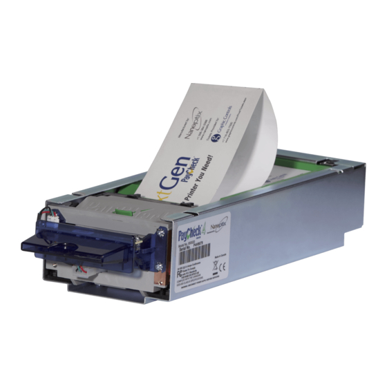
1 About the Printer 1.1 Description of Printer The Nanoptix PayCheck printer, is extremely fast, quiet, and very reliable. With thermal printing technology, there is no ribbon cassette to change, and paper loading is extremely simple. The printer is small enough to fit almost anywhere and is easy to use with the ticket exiting from the front. -
Page 8: General Specifications
Communication Interface Options Dedicated USB Comm Dedicated USB Maintenance Port Memory/Firmware PayCheck 1 & PayCheck 2: 1 Mbit of RAM, 2 Mbit flash & 16Kbit EEPROM PayCheck 3 & PayCheck 4: 2 Mbit Flash, 1 Mbit Ram & 16 kbit EEPROM Support 32 fonts Approx. -
Page 9: Paper Loading
Technicians Manual 1.3 Paper Loading The paper stack should be changed when it is low or out. Caution: The printer will not operate without paper, but it may continue to accept data from the host computer. Since the printer cannot print any transactions, the data may be lost. The maximum stack that will fit in the ticket cartridge is 200, 400, 600 or 800 tickets depending on the cartridge option that was purchased with the printer. - Page 10 Technicians Manual Open drawer. Drop ticket stack into ticket (if necessary) cartridge. Feed ticket into printer mechanism Once paper has been aligned until resistance is felt. ticket is ready to print. Figure 3: Loading Paper Document # 720004-0000 January 2011...
-
Page 11: Printer Interface Ports
Technicians Manual 1.4 Printer Interface Ports Port Identification Connector Type Function 14 pin “Molex type” RS-232 Communication USB type B USB Communication USB type B USB Maintenance 3 pin “Molex type” Bezel LED Table 2: Interface Ports USB type B 14 pin “Molex”... -
Page 12: Printer Controls
Technicians Manual 1.5 Printer Controls 1.5.1 Printer Reset (Service use only) The printer is reset by disconnecting and reconnecting the power/communication cable. Once connected, the printer goes through a startup routine and resets itself. Figure 5: Printer Reset 1.5.2 Paper Feed Button The paper feed button is used to advance the paper. -
Page 13: Firmware Selector Dip Switches
DIP switch is available through access hole in paper tray. Various firmware and setting configurations are available by selecting the 16 different DIP switch combinations. (Applies to Paycheck 3 & 4 only) Figure 7: DIP Switch (Paycheck 3 & 4 only) -
Page 14: Boot Mode Selector Dip Switches
Remove ticket tray plate to access the boot mode selector DIP switches. Different boot options are available by selecting the 4 different DIP switch combinations. (Applies to Paycheck 3 & 4 only) Figure 8: Boot Selector (Paycheck 3 & 4 only) DIP switch settings Boot source... -
Page 15: Led
FAST BLINK Print Head Error FAST BLINK Missing Black Index Mark FAST BLINK Paper Jam Table 5: LED Information Error LED Status LED Voltage LED (RED) (GREEN) (RED – PayCheck 2 only) Figure 9: LED Positions Document # 720004-0000 January 2011... -
Page 16: Testing The Printer
A test ticket similar to the one below will be printed. Pressing the button again will result in blank tickets. PayCheck 3 & Paycheck 4: To print the test ticket, the printer must be powered “ON” while holding the paper feed button for approximately 5 seconds. -
Page 17: Clearing Jams
Technicians Manual 1.7 Clearing Jams The Nanoptix PayCheck printer’s paper guide and printing mechanism roller are easily removed, giving full access to the paper path. Figure 11: Clearing Jams – Paycheck 1, 2 & 3 Figure 12: Clearing Jams – Paycheck 4... -
Page 18: Troubleshooting The Printer
Technicians Manual 2 Troubleshooting the Printer 2.1 Basic Printer Operation Although the Nanoptix PayCheck printer is a complex device, its operation is quite simple. The printer requires two consumables to operate, (1) a regulated 24 VDC power source and thermal paper. -
Page 19: Communication Cables Pin-Out
Technicians Manual 2.2 Communication Cables Pin-Out 2.2.1 Universal Communication interface The table below describes the connection pin-out for the Universal Interface (14-pin Molex) Signal Name Printer I/O Host I/O Printer Function Reset Input Output Resets Printer PRT_AUX_RXD Input Output Auxiliary Receive VAUX Input... -
Page 20: Serial Interface Connection Pin-Out
Technicians Manual 2.2.2 Serial Interface Connection pin-out The table below describes the connection pin-out for the Serial interface (12-pin Molex) Printer Signal Name Printer I/O Host I/O Function Power Input Power Input PRT_RS232_TXD Output Input Data transmit PRT_RS232_RXD Input Output Data receive No connect None... -
Page 21: Printing Problems
2.3 Printing Problems The table below can be used to determine the cause and resolution of the most common problems that may occur. If the information in this section does not correct the problem, contact a Nanoptix service representative. Problem Possible Causes... -
Page 22: Main Controller Pcb Connector Layout
Future J200 Bezel J300 Thermal Print Head J301 TPH Grounding Tab J400 Paper In J700 Motor J800 Top Of Form J1000 Daughter PCB I/O Table 10: Connector Functions Figure 14: Connector Layout (PayCheck 1 shown) Document # 720004-0000 January 2011... -
Page 23: Media And Supplies Guide
Technicians Manual 3 Media and Supplies Guide 3.1 Thermal Paper Specifications NOTE: Qualified thermal paper with the following specifications is required for proper operation. 65 mm +/-1 (2.56 IN) Width 156 mm +/- 1 (6.14 IN) Length 4.5 +0.1 -0.3 mil Thickness Brightness 2000 sec Avg. - Page 24 Technicians Manual Figure 16: Ticket Specifications Document # 720004-0000 January 2011...
-
Page 25: Ordering Thermal Paper
3.2 Ordering Thermal Paper The following paper grade produced by Appleton and Kanzaki Specialty Papers are recommended by Nanoptix. There are a number of paper converters qualified to supply this paper, provided the stacks are from these recommended grades. Paper qualification services are offered by Nanoptix for additional grades not listed below. -
Page 26: Ordering Communication Cables
The OneCheck Harness is used for communication from the CashCode bill validator to the Nanoptix Paycheck printer. The harnesses male 14-pin Molex connector plugs into the Nanoptix Paycheck printer and the female connector plugs into the host and power. The harnesses male DB9 connector plugs into the bill validator’s female DB9 connector labelled “printer”. -
Page 27: Parts List
Technicians Manual 3.4 Parts List Document # 720004-0000 January 2011... - Page 28 102904 - (Ticket Printer, LED Bezel Harness; connects LED board to panel mount 3pin) NOTE: Part numbers listed are for the PayCheck 3 printer only. Should parts for either Paycheck, Paycheck 2 or Paycheck 4 printers be required, please contact your Nanoptix service representative.
-
Page 29: Mechanical Drawings
Technicians Manual 4 Mechanical Drawings Right Side View Bottom View Document # 720004-0000 January 2011... - Page 30 Technicians Manual Front View Top View Figure 17: Mechanical Dimensions Document # 720004-0000 January 2011...
-
Page 31: Spare Parts Replacement Instructions
2. Disconnect flat cable Figure 18: Main Bracket Instruction B: Removal of the ticket tray Paycheck 1, 2 & 3: Lift on access tab, Remove ticket tray Paycheck 4: Remove mounting screw and slide tray to the right Figure 19: Ticket Tray... - Page 32 Technicians Manual Instruction C: Removal of the base plate (Paycheck 1, 2 & 3 only) Remove Tinnerman screw (using ¼ inch nut driver) and slide base plate back Figure 20: Base Plate Instruction D: Removal of flat cable 1. Disconnect the main controller PCB end of the cable by following Instruction A...
- Page 33 Technicians Manual 2. Disconnect daughter PCB end of the cable: 1. Remove the two cable retainers 2. Remove the universal daughter PCB by removing the four mounting screws 3. Unlatch cable by lifting the two side connector tabs Figure 22: Flat Cable B Document # 720004-0000 January 2011...
- Page 34 Technicians Manual Instruction E: Removal of the universal daughter PCB 1. Remove the main bracket by following Instruction A 2. Remove the universal daughter board by removing the 4 mounting screws 3. Remove cable by unlatching the two side tabs of the connector Figure 23: Daughter PCB Document # 720004-0000 January 2011...
- Page 35 4. Remove the 2 mounting screws 5. Lift printing mechanism straight up 6. Disconnect motor connector 7. Disconnect mech grounding tab using “long nose” pliers Figure 24: Printing Mechanism – Paycheck 1, 2 & 3 Document # 720004-0000 January 2011...
- Page 36 3. Remove the blue top paper guide (not shown) 4. Remove the 2 mounting screws 5. Lift printing mechanism straight up 6. Disconnect motor and paper guide connector 7. Disconnect mech grounding tab using “long nose” pliers Figure 25: Printing Mechanism Paycheck 4 Document # 720004-0000 January 2011...
- Page 37 Technicians Manual Instruction G: Removal of the main controller PCB 1. Remove the printing mechanism kit by following Instruction F 2. Disconnect bezel & paper guide harnesses 3. Disconnect flat cable 4. Remove 4 mounting screws Figure 26: Main PCB Document # 720004-0000 January 2011...
- Page 38 Technicians Manual Instruction H: Removal of paper guide kit (Paycheck 1, 2 & 3 only) 1. Remove the printing mechanism kit by following Instruction F 2. Pry one side and hold 3. Keeping an upwards pressure, push on the other side’s tab 4.
-
Page 39: Paper
For Paycheck 1, 2 & 3 1. Remove paper guide kit by following Instruction H 2. Remove PCB by carefully prying latch Figure 28: Paper Guide Sensor – Paycheck 1, 2 & 3 For Paycheck 4 1. Remove print mechanism kit by following Instruction F 2. - Page 40 4. Remove the Axiohm mount by remove the 2 mounting screws 5. Remove the mech mount by removing the mounting screw 6. Remove Front Axiohm module by removing mounting screw Figure 30: Mech Kit – Paycheck 4 Document # 720004-0000 January 2011...
- Page 41 7. Cut tie wrap 8. Remove mech mount mounting screw (Paycheck 1, 2 & 3 only) 9. Separate mechanism by sliding mount upwards (Paycheck 1, 2 & 3 only) 10. Push sensor out using a screw driver 11. Remove print head by prying with a small screw driver (Make sure not to apply any pressure to the print head white flat cable) 12.
-
Page 42: Printer Maintenance Instructions
6 Printer Maintenance Instructions Note: Under normal operating conditions, the minimum interval for cleaning the Nanoptix PayCheck printer is 3 months or 5 km of paper printed, which ever comes first. 1. Slide printer drawer open and remove ticket tray Figure 32: Remove Ticket Tray 2. - Page 43 Technicians Manual 3. Remove paper guide cover (when in use) & top paper guide. Then press down on bottom paper guide Figure 34: Remove top paper guide 4. Remove roller by pressing down and rolling out towards front of printer Figure 35: Remove Roller 5.
- Page 44 Technicians Manual 6. Clean paper guide sensor using cotton swab Figure 37: Clean paper guide sensor using cotton swab 7. Make sure that bottom paper guide can move up and down freely. Ensure that the gaps pointed by the arrows are equal and measures approximately ½...
- Page 45 Technicians Manual 8. Visually inspect the two inner sides of the bottom paper guide. If excessive wear is visible (deep grooves caused by paper), bottom paper guide should be replaced Good Replace 9. Clear dust off gears using light brush Figure 39: Clear dust off gears using light brush 10.
-
Page 46: Service & Support
Technicians Manual 7 Service & Support 7.1 Returning printers back to Nanoptix for repairs (RMA) • Send repair approval request to Nanoptix Inc. which should include: Printer model # Serial # Brief problem description • Ship defective products to Nanoptix Inc.
Need help?
Do you have a question about the PayCheck and is the answer not in the manual?
Questions and answers