
Related Manuals for Thermal Dynamics 39 Cutmaster


Summary of Contents for Thermal Dynamics 39 Cutmaster
-
Page 1: Service Manual
™ CUTMASTER PLASMA CUTTING SYSTEM Service Manual Rev. AA Date: September 17, 2007 Manual # 0-4976 Operating Features: 208-... - Page 3 Manufacturer assumes no liability for its use. Plasma Cutting Power Supply CutMaster™ 39 SL60 1Torch™ Service Manual Number 0-4976 Published by: Thermal Dynamics Corporation 82 Benning Street West Lebanon, New Hampshire, USA 03784 (603) 298-5711 www.thermal-dynamics.com Copyright 2007 by Thermadyne Corporation All rights reserved.
- Page 4 This Page Intentionally Blank...
-
Page 5: Table Of Contents
TABLE OF CONTENTS SECTION 1:GENERAL INFORMATION ...................1-1 1.01 Notes, Cautions and Warnings ..............1-1 1.02 Important Safety Precautions ..............1-1 1.03 Publications....................1-3 1.04 Note, Attention et Avertissement ..............1-3 1.05 Precautions De Securite Importantes ............1-4 1.06 Documents De Reference ................1-5 1.07 Statement of Warranty ................1-7 SECTION 2 SYSTEM:INTRODUCTION .................2-1 2.01 How To Use This Manual ................2-1... - Page 6 TABLE OF CONTENTS SECTION 5 SYSTEM: SERVICE .....................5-1 5.01 General Maintenance .................5-1 5.02 Common Faults ...................5-6 5.03 Circuit Fault Isolation ..................5-6 5.04 Main Input and Internal Power Problems ............5-7 5.05 Pilot Arc Problems ..................5-9 5.06 Main Arc Problems..................5-10 5.07 Test Procedures ..................5-10 5.08 Anti-Static Handling Procedures ...............5-12 5.09...
-
Page 7: Section 1:General Information
cutmaster 39 SECTION 1: GENERAL INFORMATION GASES AND FUMES Gases and fumes produced during the plasma cut- ting process can be dangerous and hazardous to 1.01 Notes, Cautions and Warnings your health. Throughout this manual, notes, cautions, and • Keep all fumes and gases from the breath- warnings are used to highlight important informa- ing area. - Page 8 cutmaster 39 NOISE ELECTRIC SHOCK Noise can cause permanent hearing loss. Plasma Electric Shock can injure or kill. The plasma arc arc processes can cause noise levels to exceed process uses and produces high voltage electrical safe limits. You must protect your ears from loud energy.
-
Page 9: Publications
cutmaster 39 1.03 Publications 14. American Welding Society Standard AWSF4.1, REC- OMMENDED SAFE PRACTICES FOR THE PREPARA- Refer to the following standards or their latest TION FOR WELDING AND CUTTING OF CONTAIN- ERS AND PIPING THAT HAVE HELD HAZARDOUS revisions for more information: SUBSTANCES, obtainable from the American Welding 1. -
Page 10: Precautions De Securite Importantes
cutmaster 39 1.05 Precautions De Securite • Lisez toujours les fiches de données sur la sécu- rité des matières (sigle américain “MSDS”); celles-ci Importantes devraient être fournies avec le matériel que vous utilisez. Les MSDS contiennent des renseignements quant à la quantité et la nature de la fumée et des gaz pouvant poser des dangers de santé. -
Page 11: Documents De Reference
cutmaster 39 Les incendies et les explosions peuvent résulter Nuance Minimum Nuance Suggerée Courant Arc Protective Numéro Numéro des scories chaudes, des étincelles ou de l’arc de Moins de 300* plasma. Le procédé à l’arc de plasma produit du 300 - 400* 400 - 800* métal, des étincelles, des scories chaudes pouvant * Ces valeurs s’appliquent ou l’arc actuel est... - Page 12 cutmaster 39 TRAVAIL ET DANS LES ECOLES, disponible de SURES POUR LA PRÉPARATION À LA COUPE ET l’Institut Américain des Normes Nationales (Ameri- AU SOUDAGE DE CONTENEURS ET TUYAUX AY- can National Standards Institute), 1430 Broadway, ANT RENFERMÉ DES PRODUITS DANGEREUX , New York, NY 10018 disponible auprès de la American Welding Society, 550 N.W.
-
Page 13: Statement Of Warranty
Thermal Dynamics Corporation will honor warranty claims submitted within the warranty periods listed below. All warranty periods begin on the date of sale of the product to the original retail customer or 1 year after sale to an authorized Thermal Dynamics Distributor. - Page 14 cutmaster 39 This Page Intentionally Blank GENERAL INFORMATION Manual 0-4976...
-
Page 15: Section 2 System:introduction
Operating Manual number and equipment identification numbers. Electronic copies of this manual can also be downloaded at no charge in Acrobat PDF format by going to the Thermal Dynamics web site listed below and clicking on Thermal Dynamics and then on the Literature link: http://www.thermal-dynamics.com... -
Page 16: Power Supply Specifications
cutmaster 39 2.04 Power Supply Specifications CutMaster 39 Power Supply Specifications Input Power (See Note 1) 120 VAC (± 10%), Single-Phase, 50/60 Hz 208 - 230 VAC (± 10%), Single-Phase, 50/60 Hz Power Sensing Automatic Voltage Selection. See Note 1. Input Power Cable Cable with plug, for 120VAC, 20-Amp Single-Phase input power. -
Page 17: Input Wiring Specifications
cutmaster 39 Power Supply Dimensions & Weight Ventilation Clearance Requirements Art # A-07924 Art # A-07925 15" 381 mm 24" 24" 0.6 m 0.61 m 12" 305 mm 6" 150 mm 45 lb / 20.4 kg NOTE Weight includes torch & leads, input power cord, and work cable with clamp. CAUTION Provide clearance for proper air flow through the power supply. -
Page 18: Power Supply Options And Accessories
E. SL60 Torch Ratings (Refer to Note) NOTE Ratings shown apply to the SL60 Torch only. Refer to the Specifications chart on page 2T-1 for CutMaster 39 data. F. Plasma Power Supply Used With • Thermal Dynamics CutMaster 39 INSTALLATION Manual 0-4976... -
Page 19: Section 2 Torch:introduction
cutmaster 39 SECTION 2 TORCH: 2T.03 Specifications INTRODUCTION A. Torch Configurations 1. Hand Torch, Model SL60 2T.01 Scope of Manual The hand torch head is at 75° to the torch handle. The hand torches include a torch handle and torch This manual contains descriptions, operating trigger assembly. -
Page 20: 04 Options And Accessories
cutmaster 39 2T.05 Introduction to Plasma H. Gas Requirements SL60 Torch Gas Specifications A. Plasma Gas Flow Gas (Plasma and Secondary) Compressed Air Plasma is a gas which has been heated to an ex- Operating Pressure 60 - 75 psi tremely high temperature and ionized so that it Refer to NOTE 4.1 - 5.2 bar... - Page 21 cutmaster 39 B. Gas Distribution The single gas used is internally split into plasma and secondary gases. The plasma gas flows into the torch through the negative lead, through the starter cartridge, around the electrode, and out through the tip orifice. The secondary gas flows down around the outside of the torch starter cartridge, and out between the tip and shield cup around the plasma arc.
- Page 22 cutmaster 39 This Page Intentionally Blank INTRODUCTION 2T-4 Manual 0-4976...
-
Page 23: Section 3: Installation
cutmaster 39 SECTION 3: INSTALLATION 3.01 Unpacking 1. Use the packing lists to identify and account for each item. 2. Inspect each item for possible shipping damage. If damage is evident, contact your distributor and / or ship- ping company before proceeding with the installation. 3. -
Page 24: Primary Input Power Connections
cutmaster 39 3.03 Primary Input Power Connections CAUTION Check your power source for correct voltage before plugging in or connecting the unit. The primary power source, fuse, and any extension cords used must conform to local electrical code and the recommended circuit protection and wiring requirements as specified in Section 2. -
Page 25: Gas Connections
cutmaster 39 3.04 Gas Connections A. Connecting Gas Supply to Unit The connection is the same for compressed air or high pressure gas cylinders. Refer to subsection 3.4-C if an optional air line filter is to be installed. 1. Connect the gas line to the inlet port. The illustration shows typical fittings as an example. NOTE For a secure seal, apply thread sealant to the fitting threads, according to manufacturer's instructions. - Page 26 cutmaster 39 3. Connect the gas line to the Filter. The illustration shows typical fittings as an example. NOTE For a secure seal, apply thread sealant to the fitting threads, according to the maker's instructions. Do Not use Teflon tape as a thread sealer, as small particles of the tape may break off and block the small gas passages in the torch.
-
Page 27: Torch Connections
39 3.05 Torch Connections If necessary, connect the torch to the Power Supply. Connect only the Thermal Dynamics model SL60 Torch to this power supply. WARNING Disconnect primary power at the source before connecting the torch. 1. Align the male connector (on the torch lead) with the female receptacle on the power supply. - Page 28 cutmaster 39 This Page Intentionally Blank INSTALLATION Manual 0-4976...
-
Page 29: Section 4 System:operation
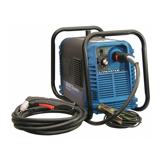
cutmaster 39 SECTION 4 SYSTEM: OPERATION 4.01 Product Features A. General Features Handle and Leads Wrap Gas Pressure Knob Torch Leads Connector Art # A-07930 Control Panel Work Cable and Clamp Manual 0-4976 OPERATION... - Page 30 cutmaster 39 B. Control Panel A-07931 1. ON / OFF Switch Controls input power to the power supply. Up is ON, down is OFF. 2. RUN / SET Switch RUN (up) position is for general torch operation. SET (down) position is for setting gas pressure and purging lines.
-
Page 31: Preparations For Operating
Check the torch for proper assembly and appropriate torch parts. The torch parts must correspond with the type of operation, and with the amperage output of this Power Supply (30 amps maximum). Use only genuine Thermal Dynamics parts with this torch. Art # A-03409 Large O-Ring, Cat. - Page 32 cutmaster 39 D. Gas Selection Ensure gas source meets requirements (refer to Section 2). Check connections and turn gas supply on. E. Connect Work Cable Clamp the work cable to the workpiece or cutting table. The area must be free from oil, paint and rust. Connect only to the main part of the workpiece;...
- Page 33 cutmaster 39 G. Set Operating Pressure Place the Power Supply RUN / SET switch to the SET (down) position. Gas will flow. Adjust gas pressure to 65 psi / 4.5 bar. Gas indicator turns on. NOTE If gas regulator leaks, reset gas pressure to 0 psi, then reset to 65 psi / 4.5 bar. 65 psi / 4.5 bar A-07933 A-07927...
- Page 34 cutmaster 39 Cutting Operation Refer to Section 1, Important Safety Precautions. Wear heavy welding gloves and protective clothing. Protect eyes with appropriate shielding. Aim the torch head away from yourself. Slide the trigger release to the rear. Squeeze and hold the trigger. Gas flows for approximately 1 second, then shuts off briefly. The pilot arc then starts.
-
Page 35: Sequence Of Operation
cutmaster 39 4.03 Sequence of Operation The following is a typical sequence of operation for this power supply. Refer to Appendix 1 for block diagram. 1. Plug the input power cord into an active circuit. a. AC power is available at the Power Supply. 2. - Page 36 cutmaster 39 This Page Intentionally Blank OPERATION Manual 0-4976...
-
Page 37: Section 4 Torch:operation
cutmaster 39 SECTION 4 TORCH: NOTE Refer to Appendix Pages for additional informa- OPERATION tion as related to the Power Supply used. Power On 4T.01 Introduction Place the ON - OFF Switch on the Power Supply to This section provides a description of the SL60 the ON position. -
Page 38: 05 Cut Quality
cutmaster 39 4T.05 Cut Quality NOTE Refer to Section 6 and the Appendix Pages for NOTES additional information on torch parts. Cut quality depends heavily on setup and pa- Change the torch parts for a different operation as rameters such as torch standoff, alignment with follows: the workpiece, cutting speed, gas pressures, and operator ability. -
Page 39: 06 General Cutting Information
cutmaster 39 Top - Edge Rounding Torch Standoff Rounding on the top edge of a cut due to wearing Improper standoff (the distance between the torch from the initial contact of the plasma arc on the tip and workpiece) can adversely affect tip life as workpiece. -
Page 40: 07 Hand Torch Operation
cutmaster 39 b. For standoff cutting, hold the torch 1/8 Dross - 3/8 in (3-9 mm) from the workpiece as When dross is present on carbon steel, it is com- shown below. monly referred to as either “high speed, slow speed, or top dross”. - Page 41 cutmaster 39 NOTE Drag Cutting With a Hand Torch The gas preflow and postflow are a characteristic Drag cutting works best on metal 3/16" (4.7 mm) of the power supply and not a function of the thick or less. torch. NOTE Trigger For best parts performance and life, always use the...
- Page 42 cutmaster 39 7. Bring the torch within transfer distance to NOTE the work. The main arc will transfer to the The tip should never come in contact with the work, and the pilot arc will shut off. workpiece except during drag cutting opera- tions.
-
Page 43: 08 Recommended Cutting Speeds
cutmaster 39 4T.08 Recommended Cutting Speeds Cutting speeds vary according to torch output, the type of material being cut, and operator skill. Speeds shown are typical for this cutting system using air plasma to cut mild steel, with output current at 30 amps and torch held at 0 - 1/16"... - Page 44 cutmaster 39 Optimum torch travel speed is dependent on current setting, lead angle, and mode of operation (hand or machine torch). Current Setting Current settings depend on torch travel speed, mode of operation (hand or machine torch), and the amount of material to be removed. Lead Angle The angle between the torch and workpiece depends on the output current setting and torch travel speed.
-
Page 45: Section 5 System: Service
cutmaster 39 SECTION 5 SYSTEM: SERVICE 5.01 General Maintenance Maintain more often Warning! if used under severe Disconnect input power before maintaining. conditions Each Use Visual check of torch tip and electrode Weekly Visually inspect the cables and leads. Replace as needed Visually inspect the torch body tip, electrode and shield cup 3 Months... - Page 46 cutmaster 39 A. Each Use Check torch consumables for wear, replace if necessary. WARNING Shut off power before inspecting or removing torch parts. NOTE When operating the torch in a normal condition, a small amount of gas vents through the gap between the shield cup and torch handle.
- Page 47 cutmaster 39 B. Every three months A. Check internal air filter, replace if necessary. 1. Shut off input power; turn off the gas supply. Bleed down the gas supply. 2. Remove the upper cover screws. 3. Loosen the lower screws. Pull the cover up and away from the unit. NOTE Leave internal ground wire in place.
- Page 48 cutmaster 39 4. Pull the upper end of the drain tube off the fitting on the filter bowl 5. Unscrew the bowl. The filter element will be visible and still attached to the main body of the Regulator / Filter. 6.
- Page 49 cutmaster 39 C. O-Ring Lubrication D. Check Optional Single - Stage Filter Element, replace if necessary. An o-ring on the Torch ATC Male Connector requires lubrication on a regular basis, depending on how 1. Shut off input power. frequently the torch is disconnected and re-con- 2.
-
Page 50: Common Faults
After re- 5. Cutting current too low. pairs are complete, run the following tests again 6. Non - Genuine Thermal Dynamics to verify that the unit is fully operational. parts used 7. Incorrect gas pressure A. -
Page 51: Main Input And Internal Power Problems
cutmaster 39 C. Pilot Arc Test C. Fan does not operate; AC indicator is OFF 1. Close the torch switch and check the fol- 1. Front Panel ON/OFF switch in OFF lowing: (down) position • Gas flows briefly, then stops. a. Place switch to ON (up) position. • Gas flow re-starts; pilot arc starts. DC 2. - Page 52 cutmaster 39 2. Dirty or defective starter cartridge D. AC indicator flashing, TEMP indicator OFF a. Check starter cartridge; clean or replace (on system start-up); RUN / SET switch in RUN position as needed. 3. Wire E8 not connected to PC Board termi- 1.
-
Page 53: Pilot Arc Problems
cutmaster 39 4. Faulty PC board 5.05 Pilot Arc Problems a. Leave RUN/SET switch in SET posi- Locate your symptom below: tion. Disconnect wire harness from A. No pilot arc; Gas flows continuously; AC terminal J1 on PC board. Test voltage indicator ON;... -
Page 54: Main Arc Problems
cutmaster 39 5.07 Test Procedures D. No gas flow; AC and GAS indicators ON, TEMP and DC indicators OFF The test procedures in this subsection are refer- 1. Upper O-ring on torch head is in wrong po- enced in the troubleshooting section. sition. - Page 55 cutmaster 39 B. Opening Power Supply Enclosure C. Diode Testing Basics The cover of the Power Supply must be removed Testing of diode modules requires a digital volt/ to gain access to the input power connections. ohmmeter that has a diode test scale. Remember that even if the diode module checks good, it may still be bad.
-
Page 56: Anti-Static Handling Procedures
cutmaster 39 6. Reverse the meter leads across the diode Disconnect primary input power. With an ohm- for reverse bias testing (refer to following meter set on the diode range, make the following figure). A properly functioning diode will checks on both diode bridges: block in the reverse bias direction and de- CutMaster 38 Diode Bridge Check pending on the meter function will indicate Meter (+) Meter (-) -
Page 57: Parts Replacement - General Information
cutmaster 39 Before disassembling any part of the Power B. Procedure Supply first read the procedure for the part to be 1. Open the wrist strap and unwrap the first replaced, then proceed with the disassembly two folds of the band. Wrap the adhesive side firmly around your wrist. 5.10 Major External Parts 2. Unroll the rest of the band and peel the Replacement liner from the copper foil at the opposite Refer to Section 6 for Major External Replace-... - Page 58 cutmaster 39 9. Connect the input power cable to the power. Test the Power Supply for proper replacement switch, with the wires posi- operation. tioned as noted previously. 5.06 Left Side Internal Parts Replace- 10. Transfer wires E1 and E2 to the replace- ment ment switch.
-
Page 59: Rear Panel Parts Replacement
cutmaster 39 A. Pressure Gauge Replacement Thermal Pad 1. Disconnect the gas input line from the Power Supply. 2. Remove the cover per Subsection 5.07-B. E16A 3. Disconnect the gas tube from the Pressure Diode Bridge 1 Switch Assembly Adapter Fitting. Hold E14A a wrench or similar tool against the lock- E15A... -
Page 60: Right Side Internal Parts Replacement
cutmaster 39 14. Reinstall the Power Supply cover. Con- 5.13 Right Side Internal Parts nect the gas input line to the inlet port. Replacement Connect the Power Supply to primary input Refer to Section 6 for Right Side Internal power. Parts List and overall detailed drawing. - Page 61 cutmaster 39 B. Pressure Switch Replacement 1. Remove the cover per Subsection 5.04-A. 2. Label and disconnect the wires to the Pres- sure Switch. 3. Turn the Pressure Switch to remove it from the Regulator/Filter Assembly. 4. Apply thread sealant to the threads of the replacement Pressure Switch.
- Page 62 cutmaster 39 This Page Intentionally Blank SERVICE 5-18 Manual 0-4976...
-
Page 63: Section 5 Torch:service
cutmaster 39 SECTION 5 TORCH: O-Ring Lubrication SERVICE An o-ring on the Torch ATC Male Connector requires lubrication on a scheduled basis. This will allow the o-ring to remain pliable and provide a proper seal. The o-ring will dry out, becoming hard and cracked, 5T.01 General Maintenance if the o-ring lubricant is not used on a regular basis. -
Page 64: 02 Inspection And Replacement Of Consumable Torch Parts
cutmaster 39 5T.02 Inspection and Replacement 3. Remove the tip. Check for excessive wear (indi- cated by an elongated or oversized orifice). Clean of Consumable Torch Parts or replace the tip if necessary. Good Tip Worn Tip WARNINGS Disconnect primary power to the system before disassembling the torch or torch leads. -
Page 65: Section 6:Parts Lists
cutmaster 39 SECTION 6: PARTS LISTS 6.01 Introduction A. Parts List Breakdown The parts list provides a breakdown of all replaceable components. B. Returns If a product must be returned for service, contact your distributor. Materials returned without proper authorization will not be accepted. 6.02 Ordering Information Order replacement parts by catalog number and complete description of the part or assembly, as listed in the parts list for each type item. -
Page 66: Major External Replacement Parts
cutmaster 39 6.05 Major External Replacement Parts Item # Description Catalog # Cover with labels 9-0173 Base Enclosure Assembly 9-0174 Tube, roll handle 9-0121 Front Panel 9-0175 Rear Panel 9-0176 Art # A-08110 NOTE Illustration may vary slightly from unit. PARTS LISTS Manual 0-4976... -
Page 67: Front Panel Replacement Parts
cutmaster 39 6.06 Front Panel Replacement Parts Item# Description Ref. Catalog # On/Off Switch 8-4248 Output Current Control Potentiometer with wire harness 9-8629 Run/Set Switch 9-1042 Output Current Control Knob 9-8527 Work Cable with Clamp, 20 Ft / 6.1 m 9-8642 Art # A-08113 NOTE... -
Page 68: Left Side Replacement Parts
cutmaster 39 6.07 Left Side Replacement Parts Item # Description Catalog # PCB Assembly 9-0178 Diode Bridge BR1, BR2 7-3345 Thermal Pad 9-4466 Input Power Cable with plug, for non-CE units 9-8660 Input Power Cable for CE units 9-8671 Input Power Cable for (CE) Australian units 9-8663 Not Shown: Power Cable Strain Relief, for all units... -
Page 69: Right Side Replacement Parts
cutmaster 39 6.08 Right Side Replacement Parts Item # Description Catalog # Console ATC Assembly 9-8641 Regulator/Filter Assembly (includes Pressure Switch, 9-0180 Pressure Gauge, Solenoid) Pressure Gauge 9-0181 Pressure Switch 9-1044 Regulator/Filter Replacement Element 9-0182 Regulator Mounting Nut 9-0183 Assembly, Output Inductor 9-8626 PFC Choke 9-8627... -
Page 70: Options And Accessories
cutmaster 39 6.09 Options and Accessories Description Catalog # 120V, 15 - Amp Plug 9-8644 120V, 20 - Amp Receptacle 9-8645 Single - Stage Filter Kit (includes Filter & Hose) 7-7507 Replacement Filter Body 9-7740 Replacement Filter Hose (not shown) 9-7742 Replacement Filter Element 9-7741... -
Page 71: Appendix 1: Sequence Of Operation(Block Diagram
cutmaster 39 APPENDIX 1: SEQUENCE OF OPERATION (BLOCK DIAGRAM) ACTION ACTION ACTION ACTION ACTION ON / OFF switch Connect work cable Close external RUN / SET switch to SET. RUN / SET switch to ON. to RUN. to workpiece. disconnect switch. RESULT Set output amperage RESULT... -
Page 72: Appendix 2: Data Tag Information
cutmaster 39 APPENDIX 2: DATA TAG INFORMATION West Lebanon, NH USA 03784 Manufacturer's Name and/or Logo, Location, Model and Revision Level, Serial Number Model: and Production Code Date of Mfr: Made in USA Type of Power Regulatory Standard Covering Supply (Note 1) This Type of Power Supply Output Current Type Duty Cycle Factor... -
Page 73: Appendix 3: Main Power Pc Board Layout
cutmaster 39 APPENDIX 3: MAIN POWER PC BOARD LAYOUT TP16 MAIN PCB ASSEMBLY 19X1773 REV OVER-TEMP PRESSURE RUN/SET TEST TEMP E14B E14A TP20 TORCH SWITCH E15B E15A TP101 E12A TP23 TP23 TP24 E12A E12B TP26 E12B TP26 E16B E16A E16B PILOT E16A TP24... -
Page 74: Appendix 4: Main Pc Board Wiring
cutmaster 39 APPENDIX 4: MAIN PC BOARD WIRING To Temperature To Pressure Sensor To Fan Switch To Solenoid MAIN PCB ASSEMBLY 19X1773 REV OVER-TEMP PRESSURE RUN/SET TEST To Current Control To Torch TEMP Receptacle To Run / Set Switch TP20 TORCH SWITCH To PFC... -
Page 75: Appendix 5: Torch Connector Diagram
cutmaster 39 APPENDIX 5: TORCH CONNECTOR DIAGRAM ATC Female Receptacle ATC Male Connector Front View Front View Negative / Negative / Plasma Plasma 8 - Open 8 - Open 4 - Green / Switch 4 - Switch 3 - Switch 7 - Open 7 - Open 3 - White /... -
Page 76: Appendix 6: System Schematic
cutmaster 39 APPENDIX 6: SYSTEM SCHEMATIC PFC INDUCTOR INPUT 230V ONLY TEST E M C FILTER E12A CE ONLY CHASSIS GND (E12A) (E15A) (E14A) (E1) E14A 120/208/230V INPUT (E16A) 50/60HZ (E2) E15A STUD E16A E12B BIAS (E12B) FAN1 CONVERTER 12VDC BLACK (E14B) (E15B) - Page 77 603-298-57 REL ECO 100535 2/27/03 Date: REL ECO B505 6/19/07 Information Proprietary to THERMAL DYNAMICS CORPORATION. Tuesday, May 15, 2001 Not For Release, Reproduction, or Distribution without Written Consent. Drawn:References NOTE: Unless Otherwise Specified, Resistors are in Ohms 1/4W 5%.
- Page 78 cutmaster 39 This Page Intentionally Blank. APPENDIX Manual 0-4976...
- Page 79 GLOBAL CUSTOMER SERVICE CONTACT Thermadyne USA Thermadyne Asia Sdn Bhd Lot 151, Jalan Industri 3/5A 2800 Airport Road Denton, Tx 76207 USA Rawang Integrated Industrial Park - Jln Batu Arang 48000 Rawang Selangor Darul Ehsan Telephone: (940) 566-2000 800-426-1888 West Malaysia Telephone: 603+ 6092 2988 Fax: 800-535-0557 Fax : 603+ 6092 1085...
- Page 80 Corporate Headquarters 16052 Swingley Ridge Road Suite 300 St. Louis, MO 63017 Telephone: 636-728-3000 Email: TDCSales@Thermadyne.com www.thermadyne.com...
Need help?
Do you have a question about the 39 Cutmaster and is the answer not in the manual?
Questions and answers