Advertisement
Table of Contents
General Information
TM
The 1Torch
SL60 and SL100 Torches work with most
plasma cutting power supplies. The Torches are equipped
with either O2B connectors or the Thermal Dynamics ATC
connector and are connected using various Adapter Kits
sold separately.
A label on the torch handle indicates the torch model
number. SL60 Torches provide cutting capabilities of up
to 60 amperes. SL100 Torches provide cutting capabili-
ties of up to 100 amperes. The torches use compressed
air as both the plasma and secondary gas.
The torches are suitable for drag cutting (with the torch
tip in contact with the workpiece, at up to 40 Amps out-
put); 40-100 Amp shielded drag cutting (with shielded
torch parts (cap, etc.) in contact with the workpiece);
standoff cutting; or gouging.
Refer to the Complete Assembly Replacement page for
configurations and catalog numbers.
These instructions are important for the proper installa-
tion of the Torches. Read the instructions thoroughly be-
fore attempting the installation. Keep these instructions
for reference.
Supplied Parts
The Replacement Torches include:
• Torch With Leads - 1 each
• Installation Instructions - 1 each
• Consumables (Installed on the Torch): Electrode,
Starter Cartridge, Tip, Shield Cup Body and Drag
Shield Cap)
• Standard Shield Cup
The consumable parts installed in the Torch may
not necessarily be optimized for your Power Sup-
ply or cutting application. For best results, refer
to the selection charts in this manual to choose the
proper consumables for your application.
© 2002 by Thermal Dynamics Corp., Printed in USA
January 8, 2009
NOTE
Cutting Hand Torches
Installation and Operation Instructions
Options
The following options are available. Refer to the complete
assembly replacement list for catalog numbers.
• ATC Adapter Kit (for Torches with ATC Connectors)
• Leads extensions (for Torches with ATC Connectors)
• Cutting Guide Kits
• Leather Leads Covers
• Standoff Cutting Guide
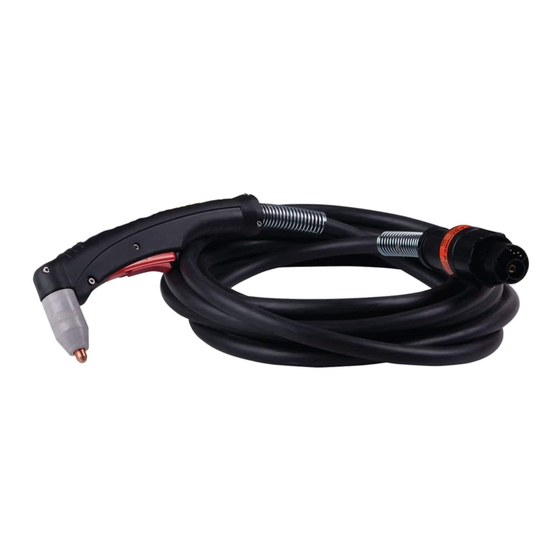
Torch Specifications
A. Torch Configurations and Dimensions
The torch head is at either 75° or 90° to the torch handle.
The torch includes a torch handle and torch trigger as-
sembly.
10.125" (257 mm)
3.75"
(95 mm)
1.17" (29 mm)
B. Torch Leads Lengths
20 foot / 6.1 m, or 50 foot / 15.2 m
For torches with ATC Connectors, leads extensions are
available to extend the leads to a maximum of 50 feet / 15.2
m. Total leads lengths must not exceed the power supply
manufacturer's recommendations.
1
Manual 0-2880
SL60 and SL100
Replacement Plasma
Art # A-03322_AB
Manual 0-2880 Rev AB
Advertisement
Table of Contents

Related Manuals for Thermal Dynamics SL60


Summary of Contents for Thermal Dynamics SL60
-
Page 1: General Information
The Torches are equipped assembly replacement list for catalog numbers. with either O2B connectors or the Thermal Dynamics ATC • ATC Adapter Kit (for Torches with ATC Connectors) connector and are connected using various Adapter Kits sold separately. -
Page 2: Connecting Torch
Arc Striking Voltage There are two types of connection for the Torch Leads. One type uses the Thermal Dynamics ATC connector. The other uses O2B connections for gas and circuitry. Both types require E. Type of Cooling an adapter kit sold separately. -
Page 3: Torch Parts Selection
Set gas pressure at the power supply regulator according to the following charts. These charts are a guide only; adjust as nec- essary for best performance. Torch Head SL60 Gas Pressure Settings Leads Length Electrode 20' / 6.1 m 50' / 15.2 m 30A, 40A, 65 psi / 4.5 bar 75 psi / 5.2 bar... - Page 4 Power Supply. DO NOT operate the Art # A-03383 SL60 Torch at more than 60 Amps, or the SL100 at more than 100 Amps. 6. Cut as usual. Simply release the trigger assembly to stop cutting.
-
Page 5: Common Operating Faults
Excessive pilot arc time d. Gas pressure too low e. Improperly assembled torch f. Non-Genuine Thermal Dynamics Parts 5. Difficult Starting a. Worn torch consumables b. Non - Genuine Thermal Dynamics Parts January 8, 2009 Manual 0-2880 Rev AB... -
Page 6: Inspection And Replacement Of Consumable Torch Parts
cutting operations (only), there may be an O-ring be- Inspection and Replacement of tween the shield cup body and drag shield cap. Do not Consumable Torch Parts lubricate the O-ring. A. General Information Drag Shield Cap WARNINGS Shield Cup Body Disconnect primary power to the system before dis- assembling the torch or torch leads. - Page 7 6 . Reinstall the Electrode by pushing it straight into the torch head until it clicks. ATC Male Connector WARNINGS Refer to the consumables selection charts for the proper combination of torch parts, including shield cups and shield caps. The use of any consumable parts other than those specified by the Manufacturer may cause irreparable damage to the torch head.
-
Page 8: Torch Consumables
Shield Cap for excellent gouging performance and en- hanced torch parts life. The Standoff Guide fits all shield cup designs for the SL60 and SL100 RPT hand torches. The Guide allows the user to easily adjust and maintain a consistent standoff height 50 - 100A for most applications. - Page 9 Consumables Selection Shield Tips: DRAG TIP Cup Body, Shield Cap, Deflector 9-8237 CUTTING 9-8243 20A 9-8205 Shield Cup 30A 9-8206 9-8218 40A 9-8207 O-Ring No. 8-3488 DRAG SHIELD CUTTING Shield Shield Cap, Drag Cup Body, Tip: 40A 9-8244 CUTTING 9-8237 Shield Cap, Deflector 40A 9-8208 9-8243...
-
Page 10: Replacement Hand Torch Parts
8-3487 Small O-Ring 8-3486 Leads Assemblies with O2B Connectors (includes switch assemblies) SL60 / 60 Amp, 20 - foot Leads Assembly with O2B connectors 4-7830 SL60 / 60 Amp, 50 - foot Leads Assembly with O2B connectors 4-7831 SL100 / 100 Amp, 20 - foot Leads Assembly with O2B connectors... - Page 11 Requires Adapter Kit For Proper Installation May Require ATC Adapter A-03323 Kit For Proper Installation January 8, 2009 Manual 0-2880 Rev AB...
-
Page 12: Complete Assembly Replacement
SL60 Hand Torch and 20 foot /6.1 m Leads, with O2B Connector 7-5200 SL60 Hand Torch and 50 foot / 15.2 m Leads, with O2B Connector 7-5201 SL60 Hand Torch and 20 foot / 6.1 m Leads, with ATC Connector 7-5204 SL60 Hand Torch and 50 foot / 15.2 m Leads, with ATC Connector... -
Page 13: Statement Of Warranty
Statement of Warranty ® LIMITED WARRANTY: Thermal Dynamics Corporation (hereinafter “Thermal”) warrants that its products will be free of defects in workmanship or material. Should any failure to conform to this warranty appear within the time period applicable to the Thermal products as stated below, Thermal shall, upon notification thereof and substantiation that the product has been stored, installed, operated, and maintained in accordance with Thermal’s specifications,...
Need help?
Do you have a question about the SL60 and is the answer not in the manual?
Questions and answers