Thermal Dynamics SL 60 Operating Manual
Cutmaster 38 power supply
Hide thumbs
Also See for SL 60:
- Installation and operation instructions manual (14 pages) ,
- Instruction manual (93 pages)

Related Manuals for Thermal Dynamics SL 60


Summary of Contents for Thermal Dynamics SL 60
- Page 1 Plasma Cutting System CutMaster 38 Power Supply SL60 Air Plasma Cutting Torch A-03286 Operating Manual June 6, 2003 Manual No. 0-2888...
- Page 3 Plasma Cutting System CutMaster 38 Power Supply Model SL60 Air Plasma Cutting Torch Operating Manual Number 0-2888 Published by: Thermal Dynamics Corporation 82 Benning Street West Lebanon, New Hampshire, USA 03784 (603) 298-5711 www.thermal-dynamics.com Copyright 2002 by Thermal Dynamics Corporation All rights reserved.
- Page 4 - temperature electric - arc metallizing torch that led to the development of a plasma torch. The fledgling company was housed in a garage in nearby Wilder, VT. In 1960, Thermal Dynamics relocated to a plant in Lebanon, NH. By this time, company sales had grown to about $1 million, largely in the areas of plasma - spraying and plasma - cutting equipment.
-
Page 5: Table Of Contents
TABLE OF CONTENTS SECTION 1: GENERAL INFORMATION ....................1-1 1.01 Notes, Cautions and Warnings ..............1-1 1.02 Important Safety Precautions ............... 1-1 1.03 Publications ....................1-3 1.07 Declaration of Conformity ................1-5 1.08 Statement of Warranty .................. 1-6 SECTION 2: SPECIFICATIONS ....................2-1 Options and Accessories .................. -
Page 7: General Information
SECTION 1: GENERAL INFORMATION 1.01 Notes, Cautions and Warnings Throughout this manual, notes, cautions, and warnings are used to highlight important information. These high- lights are categorized as follows: NOTE An operation, procedure, or background information which requires additional emphasis or is helpful in efficient operation of the system. - Page 8 • Always read the Material Safety Data Sheets (MSDS) that should be supplied with the material you are using. These MSDSs will give you the information regarding the kind and amount of fumes and gases that may be dangerous to your health. •...
-
Page 9: Publications
PLASMA ARC RAYS Plasma Arc Rays can injure your eyes and burn your skin. The plasma arc process produces very bright ultra violet and infra red light. These arc rays will damage your eyes and burn your skin if you are not properly protected. •... - Page 10 13. NWSA booklet, WELDING SAFETY BIBLIOGRAPHY obtainable from the National Welding Supply Association, 1900 Arch Street, Philadelphia, PA 19103 14. American Welding Society Standard AWSF4.1, RECOMMENDED SAFE PRACTICES FOR THE PREPARATION FOR WELDING AND CUTTING OF CONTAINERS AND PIPING THAT HAVE HELD HAZARDOUS SUBSTANCES, obtainable from the American Welding Society, 550 N.W.
-
Page 11: Declaration Of Conformity
Rigorous testing is incorporated into the manufacturing process to ensure the manufactured product meets or exceeds all design specifications. Thermal Dynamics has been manufacturing products for more than 30 years, and will continue to achieve excellence in our area of manufacture. -
Page 12: Statement Of Warranty
None Warranty repairs or replacement claims under this limited warranty must be submitted by an authorized Thermal Dynamics® repair facility within thirty (30) days of the repair. No transportation costs of any kind will be paid under this warranty. Transportation charges to send products to an authorized warranty repair facility shall be the responsibility of the customer. -
Page 13: Section 2: Specifications
DC Voltage 78 vdc 89 vdc n/a Amps Current 30 Amps 22 Amps SL 60 Torch Gas Requirements Gas Type Compressed Air Gas specifications Clean, dry, oil-free ( Note 3 ) Maximum Input Gas Pressure 125 psi / 8.6 bar Operating Gas Pressure 65 psi / 4.5 bar... -
Page 14: Options And Accessories
Electrical Requirements CutMaster 38 Input P ower R equirements P ower Input Current Input S uggested S izes (S ee Notes) Input (Amps) F use (Amps) W ire (AW G) W ire (Canada) Voltage Freq. (kVA) (Volts) (Hz) 1-Ph 1-Ph 1-Ph 1-Ph 1-Ph... -
Page 15: Torch Specifications
Voltage (V peak Arc Striking Voltage NOTE Ratings shown apply to the SL60 Torch only. Refer to the Specifications chart on page 2-1 for CutMaster 38 data. F. Plasma Power Supply Used With • Thermal Dynamics CutMaster 38 Manual 0-2888 SPECIFICATIONS... - Page 16 SPECIFICATIONS Manual 0-2888...
-
Page 17: Section 3: Installation
SECTION 3: INSTALLATION Unpacking 1. Use the packing lists to identify and account for each item. 2. Inspect each item for possible shipping damage. If damage is evident, contact your distributor and / or shipping company before proceeding with the installation. 3. -
Page 18: Primary Input Power Connections
Primary Input Power Connections CAUTION Check your power source for correct voltage before plugging in or connecting the unit. The primary power source, fuse, and any extension cords used must conform to local electrical code and the recommended circuit protection and wiring requirements as specified in Section 2. -
Page 19: Gas Connections
Gas Connections A. Connecting Gas Supply to Unit The connection is the same for compressed air or high pressure gas cylinders. Refer to subsection 3.4-C if an optional air line filter is to be installed. 1. Connect the gas line to the inlet port. The illustration shows typical fittings as an example. NOTE For a secure seal, apply thread sealant to the fitting threads, according to manufacturer's instructions. - Page 20 C. Installing Optional Single - Stage Air Filter An optional filter kit is recommended for improved filtering with compressed air, to keep moisture and debris out of the torch. 1. Attach the Single - Stage Filter Hose to the Inlet Port. 2.
- Page 21 D. Using High Pressure Gas Cylinders When using high pressure gas cylinders as the gas supply: 1. Refer to the manufacturer’s specifications for installation and maintenance procedures for high pressure gas regulators. 2. Examine the cylinder valves to be sure they are clean and free of oil, grease or any foreign material. Briefly open each cylinder valve to blow out any dust which may be present.
-
Page 22: Torch Connections
Torch Connections If necessary, connect the torch to the Power Supply. Connect only the Thermal Dynamics model SL60 Torch to this power supply. WARNING Disconnect primary power at the source before connecting the torch. 1. Align the male connector (on the torch lead) with the female receptacle on the power supply. Press the connector into the receptacle fully. -
Page 23: Operation
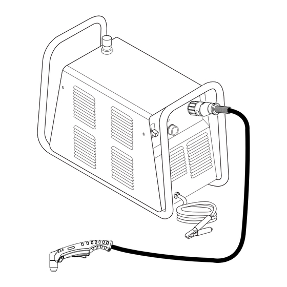
SECTION 4: OPERATION 4.01 Product Features A. General Features Gas Pressure Knob Handle and Leads Wrap Torch Leads Connector Control Panel Work Cable A-03287 and Clamp Manual 0-2888 OPERATION... - Page 24 B. Control Panel A-03283 1. ON / OFF Switch Controls input power to the power supply. Up is ON, down is OFF. 2. RUN / SET Switch RUN (up) position is for general torch operation. SET (down) position is for setting gas pressure and purging lines.
-
Page 25: Preparations For Operating
4.02 Preparations For Operating At the start of each operating session: WARNING Disconnect primary power at the source before assembling or disassembling power supply, torch parts, or torch and leads assemblies. A. Torch Parts Selection Check the torch for proper assembly and appropriate torch parts. The torch parts must correspond with the type of operation, and with the amperage output of this Power Supply (30 amps maximum). - Page 26 B. Torch Connection Check that the torch is properly connected. C. Check Primary Input Power Source 1. Check the power source for proper input voltage. Make sure the input power source meets the power re- quirements for the unit per Section 2, Specifications. 2.
- Page 27 F. Power On Place the Power Supply ON / OFF switch to the ON (up) position. AC indicator turns on. A-03384 G. Set Operating Pressure Place the Power Supply RUN / SET switch to the SET (down) position. Gas will flow. Adjust gas pressure to 65 psi / 4.5 bar.
- Page 28 H. Select Current Output Level Place RUN / SET switch to RUN (up) position. Gas flow will stop. Set the desired current output level. A-03386 Cutting Operation Refer to Section 1, Important Safety Precautions. Wear heavy welding gloves and protective clothing. Protect eyes with appropriate shielding.
- Page 29 J. Cutting Technique Hold the torch with one or two hands, with the torch tip close to the workpiece. Do not cut or handle the workpiece without welding gloves and protective clothing. Always wear protective eye shielding when cutting or gouging. Move the torch along the cut line so the arc penetrates the workpiece and sparks emerge from the bottom of the cut.
-
Page 30: Sequence Of Operation
4.03 Sequence of Operation The following is a typical sequence of operation for this power supply. Refer to Appendix 1 for block diagram. 1. Plug the input power cord into an active circuit. a. AC power is available at the Power Supply. 2. -
Page 31: Service
SECTION 5: SERVICE 5.01 General Maintenance A. Each Use Check torch consumables for wear, replace if necessary. WARNING Shut off power before inspecting or removing torch parts. NOTE When operating the torch in a normal condition, a small amount of gas vents through the gap between the shield cup and torch handle. - Page 32 B. Every three months A. Check internal air filter, replace if necessary. 1. Shut off input power; turn off the gas supply. Bleed down the gas supply. 2. Remove the upper cover screws. 3. Loosen the lower screws. Pull the cover up and away from the unit. NOTE Leave internal ground wire in place.
- Page 33 4. Pull the upper end of the drain tube off the fitting on the filter bowl. 5. Unscrew the bowl. The filter element will be visible and still attached to the main body of the Regulator / Filter. 6. Unscrew the filter element from the Regulator / Filter body. The filter element will come off with a spool and some additional pieces.
- Page 34 B. Check Optional Single - Stage Filter Element, replace if necessary. 1. Shut off input power. 2. Shut off air supply, bleed down system. 3. Disconnect gas supply hose from filter. 4. Turn the Cover counter - clockwise. 5. Remove the Filter Element from the Housing and set Element aside to dry. 6.
-
Page 35: Common Faults
Torch standoff too high from workpiece c. Worn torch parts d. Improper cutting current e. Non - Genuine Thermal Dynamics parts used 4. Short Torch Parts Life a. Oil or moisture in air source b. Exceeding system capability (material too thick) c. -
Page 36: Basic Troubleshooting Guide
5.03 Basic Troubleshooting Guide WARNING There are extremely dangerous voltage and power levels present inside this unit. Do not attempt to diagnose or repair unless you have had training in power electronics measurement and troubleshooting techniques. A. Basic Troubleshooting: Overview This guide covers basic troubleshooting. - Page 37 B. AC indicator flashing; Torch cannot be activated 1. System is in protective interlock mode. (User held torch trigger while turning on ON / OFF switch.) a. Release torch trigger, set ON / OFF switch to OFF (down). Return ON / OFF switch to ON (up) position. 2.
- Page 38 F. Torch will not pilot when torch switch is activated 1. System is in SET mode a. Change to RUN mode. 2. Upper O-ring on torch head is in wrong position. a. Remove shield cup from torch; check position of upper O-ring. Correct if necessary. A-03640 Upper Groove with Vent Holes...
- Page 39 H. Low cutting output 1. Incorrect setting of CURRENT (A) control a. Check and adjust to proper setting. 2. Faulty components in unit a. Return for repair or have qualified technician repair. I. Limited output with no control 1. Poor input or output connections a.
- Page 40 5. Torch consumables worn a. Check torch shield cup, tip, starter element, and electrode; replace as needed. 6. Faulty components in unit a. Return for repair or have qualified technician repair per Service Manual. M. No gas flow; AC indicator ON;...
-
Page 41: Parts Lists
SECTION 6: PARTS LISTS 6.01 Introduction A. Parts List Breakdown The parts list provides a breakdown of all replaceable components. B. Returns If a product must be returned for service, contact your distributor. Materials returned without proper authorization will not be accepted. 6.02 Ordering Information Order replacement parts by catalog number and complete description of the part or assembly, as listed in the parts list for each type item. -
Page 42: Options And Accessories
6.05 Options and Accessories Description Catalog # 120V, 15 - Amp Plug 9-8644 120V, 20 - Amp Receptacle 9-8645 Single - Stage Filter Kit (includes Filter & Hose) 7-7507 Replacement Filter Body 9-7740 Replacement Filter Hose (not shown) 9-7742 Replacement Filter Element 9-7741 Multi - Purpose Cart 7-8888... -
Page 43: Appendix 1: Sequence Of Operation (Block Diagram
APPENDIX 1: SEQUENCE OF OPERATION (BLOCK DIAGRAM) ACTION ACTION ACTION ACTION ACTION Close external ON / OFF switch RUN / SET switch Connect work cable RUN / SET switch to SET. to workpiece. disconnect switch. to ON. to RUN. Set output amperage RESULT RESULT RESULT... -
Page 44: Appendix 2: Data Tag Information
APPENDIX 2: DATA TAG INFORMATION West Lebanon, NH USA 03784 Manufacturer's Name and/or Logo, Location, Model and Revision Level, Serial Number Model: and Production Code Made in USA Type of Power Regulatory Standard Covering Supply (Note 1) This Type of Power Supply Output Current Type Duty Cycle Factor Output Range (Amperage/... - Page 45 This page left blank. Manual 0-2888 APPENDIX...
-
Page 46: Appendix 3: System Schematic
APPENDIX 3: SYSTEM SCHEMATIC PFC INDUCTOR INP UT 230V ONLY TEST E MC FILTER E12A CE ONLY CHASSIS GND (E12A) (E15A) (E1) (E14A) E14A 120/208/230V INPUT (E16A) 50/60HZ (E2) E15A STUD E16A E12B BIAS (E12B) FAN1 CONVERTER 12VDC BLACK (E14B) (E15B) E14B LOGIC AND CONTROL CIRCUITRY... - Page 47 W EST LEBANON, NH 03784 10/04/02 603-298-5711 REL ECO 100535 2/27/03 Date: Information Proprietary to THERMAL DYNAMICS CORPORATION. Tuesday, May 15, 2001 Not For Release, Reproduction, or Distribution without Written Consent. Drawn: References NOTE: Unless Otherwise Specified, Resistors are in Ohms 1/4W 5%.
Need help?
Do you have a question about the SL 60 and is the answer not in the manual?
Questions and answers