Thermal Dynamics A60 CUTMASTER Service Manual
Automated plasma cutting system
Hide thumbs
Also See for A60 CUTMASTER:
- Operating manual (118 pages) ,
- Operating manual (116 pages) ,
- Operating manual (98 pages)

Subscribe to Our Youtube Channel
Related Manuals for Thermal Dynamics A60 CUTMASTER


Summary of Contents for Thermal Dynamics A60 CUTMASTER
-
Page 1: Service Manual
CutmASteR ™ AutomAted PLASmA CuttING SYStem Art # A-08953_AB Service manual Rev. AQ Date: December 7, 2012 Manual # 0-4982 Operating Features: Duty Cycle... - Page 2 426-1888, or visit us on the web at www.thermal-dynamics.com. This Service Manual has been designed to instruct you on the correct use and operation of your Thermal Dynamics product. Your satisfac- tion with this product and its safe operation is our ultimate concern.
- Page 3 Manufacturer assumes no liability for its use. Plasma Cutting Power Supply CutMaster™ A60 SL100 ™ SV Automated Torch Service Manual Number 0-4982 Published by: Thermal Dynamics Corporation 82 Benning Street West Lebanon, New Hampshire, USA 03784 (603) 298-5711 www.thermal-dynamics.com Copyright 2008, 2009, 2010, 2011, 2012 by Thermadyne Corporation All rights reserved.
- Page 4 This Page Intentionally Blank...
-
Page 5: Table Of Contents
TABLE OF CONTENTS SECTION 1: GENERAL INFORMATION....................9 1.01 Notes, Cautions and Warnings ..............9 1.02 Important Safety Precautions ................ 9 1.03 Publications ....................10 1.04 Note, Attention et Avertissement ..............11 1.05 Precautions De Securite Importantes ............11 1.06 Documents De Reference ................ - Page 6 TABLE OF CONTENTS SECTION 4 TORCH: OPERATION ........................4T-1 4T.01 Machine and Automated Torch Operation ..........4T-1 4T.02 Automation Torch Parts Selection ............4T-2 4T.03 Machine and Hand Torch Parts Selection ..........4T-2 4T.04 Cut Quality ....................4T-3 4T.05 General Cutting Information ..............4T-4 4T.06 Hand Torch Operation ................4T-5 4T.07 Gouging ....................4T-8 4T.08...
- Page 7 TABLE OF CONTENTS SECTION 7: REPLACEMENT PROCEDURES ..............7-1 7.01 Scope ......................7-1 7.02 Anti-Static Handling Procedures ..............7-1 7.03 Parts Replacement - General Information ..........7-1 7.04 Major External Parts ..................7-2 7.05 Front Panel Parts Replacement ..............7-3 7.06 Left Side Internal Parts Replacement ............7-4 7.07 Rear Panel Parts Replacement ..............7-5 7.08...
- Page 8 TABLE OF CONTENTS...
-
Page 9: General Information
CUTMASTER A60 SECTION 1: • Keep all fumes and gases from the breathing area. Keep your head out of the welding fume plume. GENERAL INFORMATION • Use an air-supplied respirator if ventilation is not adequate to remove all fumes and gases. • The kinds of fumes and gases from the plasma arc depend on 1.01 Notes, Cautions and Warnings the kind of metal being used, coatings on the metal, and the different processes. -
Page 10: Publications
CUTMASTER A60 • Ventilate all flammable or explosive vapors from the workplace. 1.03 Publications • Do not cut or weld on containers that may have held combus- Refer to the following standards or their latest revisions for more tibles. information: • Provide a fire watch when working in an area where fire hazards 1. OSHA, SAFETY AND HEALTH STANDARDS, 29CFR 1910, may exist. obtainable from the Superintendent of Documents, U.S. • Hydrogen gas may be formed and trapped under aluminum Government Printing Office, Washington, D.C. 20402 workpieces when they are cut underwater or while using a water... -
Page 11: Note, Attention Et Avertissement
CUTMASTER A60 1.04 Note, Attention et Avertissement Dans ce manuel, les mots “note,” “attention,” et “avertissement” sont FUMÉE et GAZ utilisés pour mettre en relief des informations à caractère important. Ces mises en relief sont classifiées comme suit : La fumée et les gaz produits par le procédé de jet de plasma peuvent présenter des risques et des dangers de santé. NOTE •... - Page 12 CUTMASTER A60 Nuance Minimum Nuance Suggerée • Prenez des soins particuliers lorsque la zone de travail est humide Courant Arc Protective Numéro Numéro ou moite. Moins de 300* • Montez et maintenez le matériel conformément au Code électrique national des Etats-Unis. (Voir la page 5, article 9.) 300 - 400* • Débranchez l’alimentation électrique avant tout travail d’entretien 400 - 800* ou de réparation. * Ces valeurs s’appliquent ou l’arc actuel est observé...
-
Page 13: Documents De Reference
CUTMASTER A60 1.06 Documents De Reference 14. Norme AWSF4.1 de l’Association Américaine de Soudage, RECOM- MANDATIONS DE PRATIQUES SURES POUR LA PRÉPARATION À Consultez les normes suivantes ou les révisions les plus récentes ayant LA COUPE ET AU SOUDAGE DE CONTENEURS ET TUYAUX AYANT été faites à celles-ci pour de plus amples renseignements : RENFERMÉ DES PRODUITS DANGEREUX , disponible auprès de la American Welding Society, 550 N.W. LeJeune Rd., Miami, FL 1. -
Page 14: Declaration Of Conformity
* Extensive product design verification is conducted at the manufacturing facility as part of the routine design and manufacturing process. This is to ensure the product is safe, when used according to instructions in this manual and related industry standards, and performs as specified. Rigorous testing is incorporated into the manufacturing process to ensure the manufactured product meets or exceeds all design specifications. Thermal Dynamics has been manufacturing products for more than 30 years, and will continue to achieve excellence in our area of manufacture. Manufacturers responsible representative: Steve Ward Operations Director... -
Page 15: Statement Of Warranty
This warranty is exclusive and in lieu of any warranty of merchantability or fitness for a particular purpose. Thermal Dynamics will repair or replace, at its discretion, any warranted parts or components that fail due to defects in material or workmanship within the time periods set out below. Thermal Dynamics Corporation must be notified within 30 days of any failure, at which time Thermal Dynamics Corporation... - Page 16 CUTMASTER A60 This Page Intentionally Blank GENERAL INFORMATION Manual 0-4982...
-
Page 17: Section 2 System: Introduction
Electronic copies of this manual can also be downloaded at no charge in Acrobat PDF format INTRODUCTION by going to the Thermal Dynamics web site listed below and clicking on Thermal Dynamics and then on the Literature link: 2.01 How To Use This Manual http://www.thermal-dynamics.com... -
Page 18: Power Supply Specifications
CUTMASTER A60 2.04 Power Supply Specifications CutMaster A60 Power Supply Specifications 208 / 230 VAC (187 - 253 VAC), Single Phase, 60 Hz 230 VAC (187 - 253 VAC), Three Phase, 50/60 Hz 380 VAC (360 - 440 VAC), Three Phase, 50/60 Hz Input Power 400 VAC (360 - 440 VAC), Three Phase, 50/60 Hz 460 VAC (414 - 506 VAC), Single Phase, 60 Hz... -
Page 19: Input Wiring Specifications
CUTMASTER A60 2.05 Input Wiring Specifications CutMaster A60 Power Supply Input Cable Wiring Requirements Input voltage Freq Power Input Suggested Sizes Flexible Cord Volts I max I eff Fuse (amps) (Min. AWG) 1 Phase 50/60 50/60 11.8 3 Phase 50/60 11.8 Line Voltages with Suggested Circuit Protection and Wire Sizes Based on National Electric Code and Canadian Electric Code NOTE Refer to Local and National Codes or local authority having jurisdiction for proper wiring requirements. -
Page 20: Power Supply Features
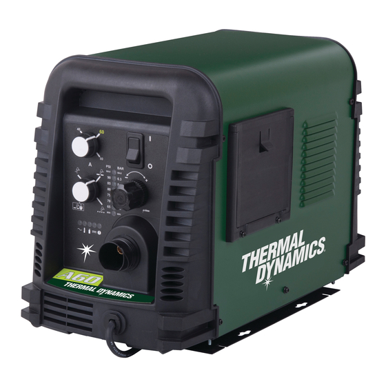
CUTMASTER A60 2.06 Power Supply Features Control Panel Art # A-08306 Torch Leads Receptacle Mounting Rails Work Cable and Clamp Automation Interface Cable Port Input Power Selection Filter Assembly Gas Inlet Port Input Power Cord Art # A-08318 INTRODUCTION Manual 0-4982... -
Page 21: Section 2 Torch: Introduction
CUTMASTER A60 SECTION 2 TORCH: 2T.03 Specifications INTRODUCTION A. Torch Configurations 1. Automation Torch, Model 2T.01 Scope of Manual The standard automation torch has a position- ing tube with rack & pinch block assembly and This manual contains descriptions, operating a solenoid valve. -
Page 22: 04 Options And Accessories
CUTMASTER A60 C. Torch Parts H. Direct Contact Hazard Starter Cartridge, Electrode, Tip, Shield Cup For standoff tip the recommended standoff is 3/16 inches / 4.7 mm. D. Parts - In - Place (PIP) 2T.04 Options And Accessories Torch Head has built - in switch For options and accessories, see section 6. - Page 23 CUTMASTER A60 E. Parts - In - Place (PIP) By forcing the plasma gas and electric arc through a small orifice, the torch delivers a high concentration The torch includes a 'Parts - In - Place' (PIP) circuit. of heat to a small area. The stiff, constricted plasma When the shield cup is properly installed, it closes arc is shown in Zone C.
- Page 24 CUTMASTER A60 This Page Intentionally Blank INTRODUCTION 2T-4 Manual 0-4982...
-
Page 25: Section 3 System: Installation
CUTMASTER A60 SECTION 3 SYSTEM: 3.03 Power Supply location and Mounting INSTALLATION NOTE 3.01 Unpacking It is recommended that the unit be secured to a suitable surface using the mounting rails. 1. Use the packing lists to identify and ac- 1. - Page 26 CUTMASTER A60 A. Cover Removal C. Input Power Selection 1. Remove the upper and lower screws which Set the Input Voltage Selection Switch at the rear secure the cover to the main assembly. Do of the unit based on the primary input voltage it not loosen the lower screws inside the cut is connected to.
- Page 27 CUTMASTER A60 9. Connect the opposite end of individual E. Connections to Single Phase Input Power wires to a customer supplied plug or main disconnect. WARNING 10. Connect the input power cable (or close the main disconnect switch) to supply Disconnect input power from the power supply power.
-
Page 28: Gas Connections
CUTMASTER A60 6. Connect the wires as follows. Filter Assembly • Remove the copper bus bar jumper from L2 and L3 on the contactor. See Inlet Port previous illustration. • Green / Yellow wire to Ground. • Remaining wires to L1, L2 and L3 in- Hose Clamp put. - Page 29 CUTMASTER A60 Installing Optional Two - Stage Air Filter Kit Filter Assembly This optional two - stage air line filter is also for use on compressed air shop systems. Filter Inlet Port removes moisture and contaminants to at least 5 microns.
- Page 30 CUTMASTER A60 Using High Pressure Air Cylinders When using high pressure air cylinders as the air supply: 1. Refer to the manufacturer’s specifications for installation and maintenance proce- dures for high pressure regulators. 2. Examine the cylinder valves to be sure they are clean and free of oil, grease or any foreign material.
-
Page 31: Section 3 Torch: Installation
2. Put the Function Control switch in the SET If necessary, connect the torch to the Power Sup- position. ply. Connect only the Thermal Dynamics model 3. Place a welding filter lens in front of the SL100SV / Automation, SL100 / Mechanical torch and turn on the air. - Page 32 CUTMASTER A60 3T.03 Setting Up Automation or Machine Torch NOTE An adapter is required to be installed in the power supply if converting a hand torch system to operate a machine or automation torch. WARNING Disconnect primary power at the source before disassembling the torch or torch leads.
-
Page 33: Section 4 System: Operation
CUTMASTER A60 SECTION 4 SYSTEM: OPERATION 4.01 Front Panel Controls / Features See Illustration for numbering Identification 1. Output Current Control Sets the desired output current. Output settings up to 60 Amps may be used for drag cutting (with the torch tip contacting the workpiece) or higher for standoff cutting. -
Page 34: Preparations For Operation
Check that the torch is properly connected. Only Set Operating Pressure Thermal Dynamics model SL60 / Manual, SL100 / 1. Place the Power Supply Function Control Mechanical or SL100 / SV Automation Torches may be connected to this Power Supply. - Page 35 CUTMASTER A60 Typical Cutting Speeds STANDOFF CutMaster A60 Gas Pressure Settings Cutting speeds vary according to torch output am- perage, the type of material being cut, and operator SL100 skill. Refer to Section 4T.08 and following for greater Leads SL60 (Mechanized Torch) details.
- Page 36 CUTMASTER A60 This Page Intentionally Blank OPERATION Manual 0-4982...
-
Page 37: Section 4 Torch: Operation
CUTMASTER A60 SECTION 4 TORCH: For optimum smooth surface quality, the travel speed should be adjusted so that only the leading OPERATION edge of the arc column produces the cut. If the travel speed is too slow, a rough cut will be produced as the arc moves from side to side in search of metal 4T.01 Machine and Automated Torch for transfer. -
Page 38: 02 Automation Torch Parts Selection
CUTMASTER A60 4T.02 Automation Torch Parts Torch Head Art # A-04173_AB Selection Electrode Check the torch for proper consumable parts. The parts supplied in the torch may not be correct for the operator’s chosen amperage level. The torch parts Start Cartridge must correspond with the type of operation. -
Page 39: 04 Cut Quality
CUTMASTER A60 4T.04 Cut Quality NOTE Refer to Section 4T.08 and following for ad- ditional information on torch parts. NOTES Change the torch parts for a different operation as Cut quality depends heavily on setup and follows: parameters such as torch standoff, align- ment with the workpiece, cutting speed, gas pressures, and operator ability. -
Page 40: 05 General Cutting Information
CUTMASTER A60 Bottom Dross Buildup Edge Starting Molten material which is not blown out of the cut For edge starts, hold the torch perpendicular to the area and resolidifies on the plate. Excessive dross workpiece with the front of the tip near (not touch- may require secondary cleanup operations after ing) the edge of the workpiece at the point where cutting. -
Page 41: 06 Hand Torch Operation
CUTMASTER A60 3. Hold the torch away from your body. 4T.06 Hand Torch Operation 4. Slide the trigger release toward the back Standoff Cutting With Hand Torch of the torch handle while simultaneously squeezing the trigger. The pilot arc will NOTE start. - Page 42 CUTMASTER A60 Drag Cutting With a Hand Torch NOTE When the shield cup is properly installed, Drag cutting works best on metal 1/4" (6 mm) thick there is a slight gap between the shield cup or less. and the torch handle. Gas vents through this gap as part of normal operation.
- Page 43 CUTMASTER A60 3. In a portion of the unwanted metal start the Trigger pierce off the cutting line and then continue the cut onto the line. Hold the torch per- pendicular to the workpiece after the pierce is complete. Trigger Release 4.
-
Page 44: 07 Gouging
CUTMASTER A60 4T.07 Gouging Current Setting Current settings depend on torch travel speed, mode of operation (hand or machine torch), and the amount of material to be removed. WARNING Lead Angle Be sure the operator is equipped with proper gloves, clothing, eye and ear protection and The angle between the torch and workpiece depends that all safety precautions at the front of this on the output current setting and torch travel speed. - Page 45 CUTMASTER A60 This Page Intentionally Blank Manual 0-4982 4T-9 OPERATION...
-
Page 46: 08 Recommended Cutting Speeds For Machine And Automated Torches With Exposed Tip
CutMaster a60 4T.08 Recommended Cutting Speeds for Machine and Automated Torches With Exposed Tip Mild Steel Air Plasma / Air Shield Starter Cartridge Standard Shield Cup Deflector Heavy Duty Starter Electrode Maximum Life Shield Cup Cartridge 9-8218 9-8213 9-8243 9-8208 9-8232 9-8237 9-8277... - Page 47 CutMaster a60 Torch Initial Kerf Width Material Gas Pressure Arc Voltage Working Travel Speed Piercing Pierce Delay @ Rec. Thickness (Air) Height Height Speed (mm) (torch lead Volts (mm) (mm/min) (mm) (sec) (mm) length) 3990 2920 1810 1470 4.8 (7.6m) 1345 5.2 (15.2m) 1100...
- Page 48 CutMaster a60 Stainless Steel Air Plasma / Air Shield Starter Cartridge Standard Shield Cup Deflector Heavy Duty Starter Electrode Maximum Life Shield Cup Cartridge 9-8218 9-8213 9-8243 9-8208 9-8232 9-8237 9-8277 Torch Initial Kerf Width Gas Pressure Material Arc Voltage Working Travel Speed Piercing...
- Page 49 CutMaster a60 Torch Initial Kerf Width Material Gas Pressure Arc Voltage Working Travel Speed Piercing Pierce Delay @ Rec. Thickness (Air) Height Height Speed (mm) (torch lead Volts (mm) (mm/min) (mm) (sec) (mm) length) 1670 1140 5.2 (7.6) 5.5 (15.2) Edge Start BOLD TYPE indicates maximum piercing parameters.
- Page 50 CutMaster a60 Aluminum Air Plasma / Air Shield Starter Cartridge Standard Shield Cup Deflector Heavy Duty Starter Electrode Maximum Life Shield Cup Cartridge 9-8218 9-8213 9-8243 9-8208 9-8232 9-8237 9-8277 Torch Initial Kerf Width Gas Pressure Material Arc Voltage Working Travel Speed Piercing Pierce Delay...
- Page 51 CutMaster a60 Torch Initial Kerf Width Material Gas Pressure Arc Voltage Working Travel Speed Piercing Pierce Delay @ Rec. Thickness (Air) Height Height Speed (mm) (torch lead Volts (mm) (mm/min) (mm) (sec) (mm) length) 7620 3500 2350 4.8 (7.6m) 2170 1740 5.2 (15.2m) 1015...
- Page 52 CutMaster a60 Mild Steel Air Plasma / Air Shield Starter Cartridge Standard Shield Cup Deflector Heavy Duty Starter Electrode Maximum Life Shield Cup Cartridge 9-8218 9-8213 9-8243 9-8210 9-8232 9-8237 9-8277 Torch Initial Kerf Width Gas Pressure Material Arc Voltage Working Travel Speed Piercing...
- Page 53 CutMaster a60 Torch Initial Kerf Width Material Gas Pressure Arc Voltage Working Travel Speed Piercing Pierce Delay @ Rec. Thickness (Air) Height Height Speed (mm) (torch lead Volts (mm) (mm/min) (mm) (sec) (mm) length) 7540 7015 0.10 4570 0.10 3650 0.20 2465 0.20...
- Page 54 CutMaster a60 Stainless Steel Air Plasma / Air Shield Starter Cartridge Standard Shield Cup Deflector Heavy Duty Starter Electrode Maximum Life Shield Cup Cartridge 9-8218 9-8213 9-8243 9-8210 9-8232 9-8237 9-8277 Torch Initial Kerf Width Gas Pressure Material Arc Voltage Working Travel Speed Piercing...
- Page 55 CutMaster a60 Torch Initial Kerf Width Material Gas Pressure Arc Voltage Working Travel Speed Piercing Pierce Delay @ Rec. Thickness (Air) Height Height Speed (mm) (torch lead Volts (mm) (mm/min) (mm) (sec) (mm) length) 10890 0.00 7560 0.10 4365 0.10 2865 0.20 2195...
- Page 56 CutMaster a60 Aluminum Air Plasma / Air Shield Starter Cartridge Standard Shield Cup Deflector Heavy Duty Starter Electrode Maximum Life Shield Cup Cartridge 9-8218 9-8213 9-8243 9-8210 9-8232 9-8237 9-8277 Torch Initial Kerf Width Gas Pressure Material Arc Voltage Working Travel Speed Piercing Pierce Delay...
- Page 57 CutMaster a60 Torch Initial Kerf Width Material Gas Pressure Arc Voltage Working Travel Speed Piercing Pierce Delay @ Rec. Thickness (Air) Height Height Speed (mm) (torch lead Volts (mm) (mm/min) (mm) (sec) (mm) length) 17010 0.00 7680 0.10 6410 0.10 5230 0.20 4010...
- Page 58 CutMaster a60 Mild Steel Air Plasma / Air Shield Starter Cartridge Standard Shield Cup Deflector Heavy Duty Starter Electrode Maximum Life Shield Cup Cartridge 9-8218 9-8213 9-8243 9-8211 9-8232 9-8237 9-8277 Torch Initial Kerf Width Gas Pressure Material Arc Voltage Working Travel Speed Piercing...
- Page 59 CutMaster a60 Torch Initial Kerf Width Material Gas Pressure Arc Voltage Working Travel Speed Piercing Pierce Delay @ Rec. Thickness (Air) Height Height Speed (mm) (torch lead Volts (mm) (mm/min) (mm) (sec) (mm) length) 8915 0.00 7415 0.10 5915 0.10 4095 0.30 3325...
- Page 60 CutMaster a60 Stainless Steel Air Plasma / Air Shield Starter Cartridge Standard Shield Cup Deflector Heavy Duty Starter Electrode Maximum Life Shield Cup Cartridge 9-8218 9-8213 9-8243 9-8211 9-8232 9-8237 9-8277 Torch Initial Kerf Width Gas Pressure Material Arc Voltage Working Travel Speed Piercing...
- Page 61 CutMaster a60 Torch Initial Kerf Width Material Gas Pressure Arc Voltage Working Travel Speed Piercing Pierce Delay @ Rec. Thickness (Air) Height Height Speed (mm) (torch lead Volts (mm) (mm/min) (mm) (sec) (mm) length) 9020 0.00 8380 0.00 7730 0.10 5865 0.20 3410...
- Page 62 CutMaster a60 Aluminum Air Plasma / Air Shield Starter Cartridge Standard Shield Cup Deflector Heavy Duty Starter Electrode Maximum Life Shield Cup Cartridge 9-8218 9-8213 9-8243 9-8211 9-8232 9-8237 9-8277 Torch Initial Kerf Width Gas Pressure Material Arc Voltage Working Travel Speed Piercing Pierce Delay...
- Page 63 CutMaster a60 Torch Initial Kerf Width Material Gas Pressure Arc Voltage Working Travel Speed Piercing Pierce Delay @ Rec. Thickness (Air) Height Height Speed (mm) (torch lead Volts (mm) (mm/min) (mm) (sec) (mm) length) 0.00 8890 8420 0.00 0.10 7170 5710 0.20 0.20...
-
Page 64: 09 Recommended Cutting Speeds For Machine And Automated Torches With Shielded Tip
CutMaster a60 4T.09 Recommended Cutting Speeds for Machine and Automated Torches With Shielded Tip Mild Steel Air Plasma / Air Shield Starter Cartridge Shield Cap Maximum Life Shield Cup Heavy Duty Starter Electrode Cartridge 9-8213 9-8245 9-8237 9-8208 9-8232 9-8277 Torch Initial Kerf Width... - Page 65 CutMaster a60 Torch Initial Kerf Width Material Gas Pressure Arc Voltage Working Travel Speed Piercing Pierce Delay @ Rec. Thickness (Air) Height Height Speed (mm) (torch lead Volts (mm) (mm/min) (mm) (sec) (mm) length) 3266 2239 1794 1651 5.2 (7.6) 1578 5.5 (15.2) 1256...
- Page 66 CutMaster a60 Stainless Steel Air Plasma / Air Shield Starter Cartridge Shield Cap Maximum Life Shield Cup Heavy Duty Starter Electrode Cartridge 9-8213 9-8245 9-8237 9-8208 9-8232 9-8277 Torch Initial Kerf Width Gas Pressure Material Arc Voltage Working Travel Speed Piercing Pierce Delay @ Rec.
- Page 67 CutMaster a60 Torch Initial Kerf Width Material Gas Pressure Arc Voltage Working Travel Speed Piercing Pierce Delay @ Rec. Thickness (Air) Height Height Speed (mm) (torch lead Volts (mm) (mm/min) (mm) (sec) (mm) length) 1670 1140 5.2 (7.6) 5.5 (15.2) BOLD TYPE indicates maximum piercing parameters.
- Page 68 CutMaster a60 Aluminum Air Plasma / Air Shield Starter Cartridge Shield Cap Maximum Life Shield Cup Heavy Duty Starter Electrode Cartridge 9-8213 9-8245 9-8237 9-8208 9-8232 9-8277 Torch Initial Kerf Width Gas Pressure Material Arc Voltage Working Travel Speed Piercing Pierce Delay @ Rec.
- Page 69 CutMaster a60 Torch Initial Kerf Width Material Gas Pressure Arc Voltage Working Travel Speed Piercing Pierce Delay @ Rec. Thickness (Air) Height Height Speed (mm) (torch lead Volts (mm) (mm/min) (mm) (sec) (mm) length) 7660 3490 2350 5.2 (7.6) 2170 1630 5.5 (15.2) 10.0...
- Page 70 CutMaster a60 Mild Steel Air Plasma / Air Shield Starter Cartridge Shield Cap Maximum Life Shield Cup Heavy Duty Starter Electrode Cartridge 9-8213 9-8238 9-8237 9-8210 9-8232 9-8277 Torch Initial Kerf Width Gas Pressure Material Arc Voltage Working Travel Speed Piercing Pierce Delay @ Rec.
- Page 71 CutMaster a60 Torch Initial Kerf Width Material Gas Pressure Arc Voltage Working Travel Speed Piercing Pierce Delay @ Rec. Thickness (Air) Height Height Speed (mm) (torch lead Volts (mm) (mm/min) (mm) (sec) (mm) length) 6804 5942 0.10 5080 0.10 3316 0.20 2794 0.20...
- Page 72 CutMaster a60 Stainless Steel Air Plasma / Air Shield Starter Cartridge Shield Cap Maximum Life Shield Cup Heavy Duty Starter Electrode Cartridge 9-8213 9-8238 9-8237 9-8210 9-8232 9-8277 Torch Initial Kerf Width Gas Pressure Material Arc Voltage Working Travel Speed Piercing Pierce Delay @ Rec.
- Page 73 CutMaster a60 Torch Initial Kerf Width Material Gas Pressure Arc Voltage Working Travel Speed Piercing Pierce Delay @ Rec. Thickness (Air) Height Height Speed (mm) (torch lead Volts (mm) (mm/min) (mm) (sec) (mm) length) 4590 0.00 3925 0.10 3285 0.10 1985 0.20 1850...
- Page 74 CutMaster a60 Aluminum Air Plasma / Air Shield Starter Cartridge Shield Cap Maximum Life Shield Cup Heavy Duty Starter Electrode Cartridge 9-8213 9-8238 9-8237 9-8210 9-8232 9-8277 Torch Initial Kerf Width Gas Pressure Material Arc Voltage Working Travel Speed Piercing Pierce Delay @ Rec.
- Page 75 CutMaster a60 Torch Initial Kerf Width Material Gas Pressure Arc Voltage Working Travel Speed Piercing Pierce Delay @ Rec. Thickness (Air) Height Height Speed (mm) (torch lead Volts (mm) (mm/min) (mm) (sec) (mm) length) 8890 0.00 8890 0.10 7070 0.10 5095 0.20 3335...
- Page 76 CutMaster a60 Mild Steel Air Plasma / Air Shield Starter Cartridge Shield Cap Maximum Life Shield Cup Heavy Duty Starter Electrode Cartridge 9-8213 9-8239 9-8237 9-8211 9-8232 9-8277 Torch Kerf Width Gas Pressure Material Initial Piercing Arc Voltage Working Travel Speed Pierce Delay @ Rec.
- Page 77 CutMaster a60 Torch Kerf Width Material Gas Pressure Initial Piercing Arc Voltage Working Travel Speed Pierce Delay @ Rec. Thickness (Air) Height Height Speed (mm) (torch lead Volts (mm) (mm/min) (mm) (sec) (mm) length) 0.00 7895 6395 0.10 4895 0.10 4025 0.30 3300...
- Page 78 CutMaster a60 Stainless Steel Air Plasma / Air Shield Starter Cartridge Shield Cap Maximum Life Shield Cup Heavy Duty Starter Electrode Cartridge 9-8213 9-8239 9-8237 9-8211 9-8232 9-8277 Torch Kerf Width Gas Pressure Material Initial Piercing Arc Voltage Working Travel Speed Pierce Delay @ Rec.
- Page 79 CutMaster a60 Torch Kerf Width Material Gas Pressure Initial Piercing Arc Voltage Working Travel Speed Pierce Delay @ Rec. Thickness (Air) Height Height Speed (mm) (torch lead Volts (mm) (mm/min) (mm) (sec) (mm) length) 0.00 9410 8120 0.00 6830 0.10 5635 0.20 4010...
- Page 80 CutMaster a60 Aluminum Air Plasma / Air Shield Starter Cartridge Shield Cap Maximum Life Shield Cup Heavy Duty Starter Electrode Cartridge 9-8213 9-8239 9-8237 9-8211 9-8232 9-8277 Torch Initial Kerf Width Gas Pressure Material Arc Voltage Working Travel Speed Piercing Pierce Delay @ Rec.
- Page 81 CutMaster a60 Torch Initial Kerf Width Material Gas Pressure Arc Voltage Working Travel Speed Piercing Pierce Delay @ Rec. Thickness (Air) Height Height Speed (mm) (torch lead Volts (mm) (mm/min) (mm) (sec) (mm) length) 0.00 9020 0.00 7595 0.10 6165 0.20 5045 5.9 (7.6m)
-
Page 82: Patent Information
CUTMASTER A60 PATENT INFORMATION Plasma Cutting Torch Patents The following parts are covered under U.S. and Foreign Patents as follows: Catalog # Description Patent(s) 9-8215 Electrode US Pat No(s) 6163008; 6987238 Other Pat(s) Pending 9-8232 Electrode US Pat No(s) 6163008; 6987238 Other Pat(s) Pending 9-8213 Cartridge... - Page 83 CUTMASTER A60 Catalog # Description Patent(s) 9-8239 Shield Cap US Pat No(s) 6914211; D496951 Other Pat(s) Pending 9-8244 Shield Cap US Pat No(s) 6914211; D505309 Other Pat(s) Pending 9-8245 Shield Cap US Pat No(s) 6914211; D496951 Other Pat(s) Pending The following parts are also licensed under U.S. Patent No. 5,120,930 and 5,132,512: Catalog # Description 9-8235...
- Page 84 CUTMASTER A60 This Page Intentionally Blank OPERATION 4T-48 Manual 0-4982...
-
Page 85: Section 5 System: Service
CUTMASTER A60 SECTION 5 SYSTEM: SERVICE 5.01 General Maintenance Maintain more often Warning! if used under severe Disconnect input power before maintaining. conditions Each Use Visual check of torch tip and electrode Weekly Visually inspect the cables and leads. Replace as needed Visually inspect the torch body tip, electrode, start cartridge and shield cup 3 Months... -
Page 86: Maintenance Schedule
3. Metal too thick. environment. 4. Worn torch parts 5. Cutting current too low. Daily Operational Checks or Every Six Cutting 6. Non - Genuine Thermal Dynamics Hours: parts used 7. Incorrect gas pressure Check torch consumable parts, replace if dam-... -
Page 87: Fault Indicator
CUTMASTER A60 5.04 Fault Indicator Explanation of Faults " UNDER PRESSURE: Indicates that operating pres- At initial power up, two lights will temporarily illu- sure is set too low and power supply output minate for 2-3 seconds to show the version of software power will be disabled. -
Page 88: Basic Troubleshooting Guide
CUTMASTER A60 5.05 Basic Troubleshooting Guide WARNING There are extremely dangerous voltage and power levels present inside this unit. Do not attempt to diagnose or repair unless you have had training in power electronics measurement and troubleshooting techniques. Problem - Symptom Possible Cause Recommended Action ON / OFF Switch is on 1. - Page 89 CUTMASTER A60 Problem - Symptom Possible Cause Recommended Action FAULT & 80 PSI 1. Torch shield cup is loose. 1. Tighten shield cup by hand. Do not overtighten. indicators flashing. 2. Torch tip, electrode or starter 2. Turn OFF power supply. Remove shield cup. Install Gas flow is cycling on cartridge missing. missing parts. and OFF. 3. Torch start cartridge is stuck. 3. Turn OFF power supply. Bleed down system pressure.
-
Page 90: Circuit Fault Isolation
CUTMASTER A60 5.06 Circuit Fault Isolation B. Cover Installation 1. Reverse previous procedures for cover installa- tion. WARNING NOTE The following procedures should not be at- When installing the upper screws, attempt to tempted by anyone who has not had proper reuse the original threads. - Page 91 CUTMASTER A60 D. Initial Set up Conditions DRAG CutMaster A-60 Gas Pressure Settings This section is to help isolate the defective circuit before troubleshooting, identify symptoms, and test Leads SL60 SL100 the unit for proper operation. Follow the instructions Length (Hand Torch) (Mechanized Torch) as given to identify the possible symptom(s) and the...
- Page 92 CUTMASTER A60 G. Main Arc and Controls Test 10. While cutting keep the CNC Start signal active or the Remote Pendant or Torch switch closed and Connect work Cable to the work piece, Close torch bring the torch OFF the edge of the material. switch (Pendant switch or activate CNC Start) to es- •...
-
Page 93: Main Input And Internal Power Problems
CUTMASTER A60 4. There are three (3) ARC VOLTs signals available Three-Phase (3ø) and Jumper Settings from the J6 connector. Store copper jumper in spare parts box a) J2-9 (+) to J2-7 (-) Jumper L1 -L4 b) J2-5 (+) to J2-6 (-) (Auto Interface PCB J3 con- nector with jumper installed between pins 1 and 2) = ARC VOLTS divided by 50 c) J2-5 (+) to J2-6 (-) (Auto Interface PCB J3 con-... - Page 94 CUTMASTER A60 D. All front panel indicators are OFF, fans b) With all power removed from the unit, dis- connect the ribbon cable from J2 connector on do not run. Main Contactor W1 does not Main PCB. Check continuity between J2-34 to close.
- Page 95 CUTMASTER A60 G. TRIGGER LOCKED DURING POWER UP 3. Starter Cartridge is stuck. FAULT. The FAULT Indicator and 75 PSI a) Turn OFF power supply. Bleed down the sys- LED is flashing. tem. Remove the shield cup, tip,start cartridge and electrode. Check the lower end unit of the 1.
- Page 96 CUTMASTER A60 J. AC LED ON, TEMP, GAS, DC LED's are N. AC LED ON, TEMP LED OFF, GAS LED OFF, FAULT Indicator is flashing. ON, Gas does not flow in SET mode using PRESSURE LED is flashing. Gas is not a machine torch with remote solenoid.
-
Page 97: Pilot Arc Problems
CUTMASTER A60 5.08 Pilot Arc Problems A. AC LED ON, TEMP LED OFF, GAS LED ON. Nothing happens when torch switch or remote switch is closed ( Or CNC Upper Groove with Vent Holes START signal is active) No gas flow, DC Must Remain Open LED OFF. -
Page 98: Main Arc And Controls Problems
CUTMASTER A60 5.09 Main Arc and Controls C. AC LED ON, TEMP LED OFF, GAS LED ON, gas flowing, DC LED OFF, Fault Problems Indicators OFF, No arc in torch A. Main arc will not establish, LED D59 ON Defective Logic PCB Main PCB remains ON while pilot arc is a) Measure voltage at Main PCB between test striking the work piece. -
Page 99: Cnc Interface Problems
CUTMASTER A60 5.10 CNC Interface Problems CutMaster 52 & 82 Cover Screws W1 contactor wired for 1PH A. Nothing happens when jumper is installed Actuator Button between J2-3 to J2-4. Actuator Arm 1. Defective Automation Interface PCB (PCB 4) a) Measure voltage on PCB 4 between J1-6 to J1-8 for 12VDC. - Page 100 CUTMASTER A60 C. Input Capacitor PCB Test IGBT B Meter (+) Meter (-) Indication Using an ohmmeter check continuity between the following points: PRI 3 (C) MTH 6 Forward Bias PRI 3 (C) MTH 5 Reverse Bias Input Capacitors MTH 6 PRI 3 (C) Reverse Bias Meter +...
- Page 101 CUTMASTER A60 MTH1 MTH8 MTH7 MTH5 MTH6 MTH3 MTH4 MTH2 Art # A-08841 *J3 CONNECTOR PINOUT CAPACITOR PCB SIGNALS Signal Source-Destination J1-1 Capacitor bank A+ J1-5 Capacitor bank A- J2-1 Capacitor Bank B+ J2-5 Capacitor Bank B- J3-1 +12 VDC J3-2 /460 Active low for 460VAC input J3-3...
- Page 102 CUTMASTER A60 LOGIC PCB LAYOUT PCB3 D1 TP3 *J1 Pinout Art # A-08179 LOGIC PCB SIGNALS (Same for MAIN PCB J2) Signal Source/Destination J1-1 -VOUT (-) OUTPUT VOLTAGE J1-2 /TIP VOLTS Active high when tip is installed J1-3 TIP_SEN Approx. 100VDC while cutting with tip not in contact w/work piece, Active low when tip contact work during cut (Drag Mode) J1-4...
- Page 103 CUTMASTER A60 J1-9 /W1_ON Active low to enable W1 contactor J1-10 SHDN Active low enables PWM circuit J1-11 /TRCH_SOL Active low to enable Torch Solenoid J1-12 /SOL_ON Active low to enable Power Supply solenoid J1-13 /OK_TO_MOVE Active low to enable OK_TO_MOVE (CNC) J1-14 /FAN_ON Active low to enable fans...
- Page 104 CUTMASTER A60 LED INDICATORS NORMAL INDICATION FIRMWARE VERSION ERROR MESSAGE +12VDC MAX PRESSURE Over Pressure 90 PSI Internal Error 85 PSI Shorted torch 80 PSI Tip Missing 75 PSI Start Signal active during power up 70 PSI Parts-In-Place Fault (PIP) 65 PSI Input Power Fault MIN PRESSURE...
- Page 105 CUTMASTER A60 This Page Intentionally Blank Manual 0-4982 5-21 SERVICE...
- Page 106 CUTMASTER A60 *J2 PINOUT PRI_4 J4 J3 I_DMD1 PRI_1 GND1 PRI_3 PRI_2 TIP1 SEC1 ELECTRODE1 +48V2 +12V2 -V_OUT1 +48V1 J8 J7 J6 J5 Art # A-08518_AB CHOKE1 SEC2 GND2 +12V1 WORK_1 SERVICE 5-22 Manual 0-4982...
- Page 107 CUTMASTER A60 MAIN PCB SIGNALS LED INDICATORS D59 PCR Indicates Pilot IGBT gate signal is on J1-1 L1 Primary AC Line D78 CSR Indicates cutting arc has been established J1-2 Not used J1-3 Not used MAIN PCB TEST POINTS J1-4 Not used GND1 Common...
- Page 108 CUTMASTER A60 This Page Intentionally Blank SERVICE 5-24 Manual 0-4982...
-
Page 109: Section 5 Torch: Service
CUTMASTER A60 SECTION 5 TORCH: SERVICE Upper Groove 5T.01 General Maintenance with Vent Holes Must Remain Open NOTE Upper O-Ring in Correct Groove Refer to Previous "Section 5 System" for com- mon and fault indicator descriptions. Threads Cleaning Torch Lower O-Ring Art # A-03725 Torch Head O-Ring Even if precautions are taken to use only clean air... -
Page 110: 02 Inspection And Replacement Of Consumable Torch Parts
CUTMASTER A60 5T.02 Inspection and Replacement 4. Remove the tip. Check for excessive wear (indi- cated by an elongated or oversized orifice). Clean of Consumable Torch Parts or replace the tip if necessary. Good Tip Worn Tip WARNING Disconnect primary power to the system be- fore disassembling the torch or torch leads. -
Page 111: Parts Lists
CUTMASTER A60 SECTION 6: PARTS LISTS 6.01 Introduction A. Parts List Breakdown The parts list provide a breakdown of all replaceable components. The parts lists are arranged as follows: Section "6.03 Power Supply Replacement" Section "6.04 Replacement Power Supply Parts" Section "6.05 Options and Accessories"... -
Page 112: Replacement Power Supply Parts
CUTMASTER A60 6.04 Replacement Power Supply Parts Description Catalog # Regulator 9-0115 Filter Assembly Replacement Element 9-0116 Input Power Cord for 208 / 230 V Power Supply 9-8596 Input Power Cord for 400 V Power Supply 9-0218 Input Power Cord for 460/600V Power Supply 9-8593 6.05 Options and Accessories Description... - Page 113 CUTMASTER A60 Intentionally Blank Manual 0-4982 PARTS LIST...
-
Page 114: Major External Replacement Parts
CUTMASTER A60 6.06 Major External Replacement Parts Item # Description Catalog # Cover with labels 9-0128 Base Enclosure 9-0118 Power Supply Mounting Bracket 9-9386 Front Panel 9-0127 Rear Panel 9-0101 Art # A-08321 NOTE Illustration may vary slightly from unit. PARTS LIST Manual 0-4982... -
Page 115: Front Panel Replacement Parts
CUTMASTER A60 6.07 Front Panel Replacement Parts Item# Description Ref. Catalog # Output Current Control and Function Control Knobs 9-8527 Toggle - On/Off Switch SW1 9-0109 Work Cable with Clamp, 20 Ft / 6.1 m 9-0184 Art # A-08123 NOTE Illustration may vary slightly from unit. Manual 0-4982 PARTS LIST... -
Page 116: Left Side Replacement Parts
CUTMASTER A60 6.08 Left Side Replacement Parts Item # Description Catalog # Main PCB Assembly non 600V PCB 1 9-0125 Main PCB Assembly 600V Only PCB 1 9-0166 Logic PCB PCB 3 9-0107* Center Chassis Molded Plastic 9-0102 Fan, MOT 1, MOT 2 9-0104 Transformer, Main Non 600V 9-0199... -
Page 117: Right Side Replacement Parts
CUTMASTER A60 6.09 Right Side Replacement Parts Item # Description Catalog # Contactor, 4 Pole 9-8587 Solenoid, 12V 9-0114 Spare Parts Box 7-3267 Spare Parts Box Cover 7-3266 Console Quick Disconnect 9-0161 Regulator, with knob and mounting nut 9-0115* Assembly, PCB, Input Capacitors non 600V 9-0126 Assembly, PCB, Input Capacitors 600V Only 9-0163... -
Page 118: Torch Replacement Parts Sl100Sv Torch (With Solenoid On Mounting Tube)
CUTMASTER A60 6.10 Torch Replacement Parts SL100SV Torch (with Solenoid on Mounting Tube) Item No. Description Catalog No. Torch Head Assembly without leads (includes items 2, 3, and 14) 9-8220 Large O-Ring 8-3487 Small O-Ring 8-3486 PIP Switch Kit 9-7036 PIP Plunger and Return Spring Kit 9-7045 Automated Leads Assemblies with ATC connectors... - Page 119 CUTMASTER A60 Art # A-07113 Manual 0-4982 PARTS LIST...
-
Page 120: Torch Consumable Parts Automation / Machine (Sl100)Torch
CUTMASTER A60 6.11 Torch Consumable Parts Automation / Machine (SL100)Torch Ohmic Clip Automation Torch Ohmic Clip 9-8224 Manual Torch 9-8259 20-40A Shield Tip: Shield Cap, Machine Cup Body, STANDOFF 40A 9-8245 9-8237 CUTTING 9-8205 Shield Cap, Deflector Shield Cup 9-8206 9-8243 9-8218 9-8208... - Page 121 CUTMASTER A60 Intentionally Blank Manual 0-4982 6-11 PARTS LIST...
-
Page 122: Torch Consumable Parts Manual (Sl60)Torch
CUTMASTER A60 6.12 Torch Consumable Parts Manual (SL60)Torch Tips: Shield DRAG TIP Cup Body, Shield Cap, Deflector 9-8237 CUTTING 9-8243 20A 9-8205 30A 9-8206 Shield Cup 40A 9-8207 9-8218 60A 9-8252 O-Ring No. 8-3488 Shield Cap, Drag DRAG SHIELD 40A 9-8244 CUTTING Shield Cup Body,... -
Page 123: Replacement Parts For Hand Torch
CUTMASTER A60 6.13 Replacement Parts for Hand Torch Item # Description Catalog # Torch Handle Replacement Kit (includes items No. 2 & 3) 9-7030 Trigger Assembly Replacement Kit 9-7034 Handle Screw Kit (5 each, 6-32 x 1/2” cap screw, and wrench) 9-8062 Torch Head Assembly Replacement Kit (includes items No. 5 & 6) 9-8219 Large O-Ring 8-3487 Small O-Ring 8-3486 Leads Assemblies with ATC connectors (includes switch assemblies) SL60, 20 - foot Leads Assembly with ATC connector... - Page 124 CUTMASTER A60 Intentionally Blank PARTS LIST 6-14 Manual 0-4982...
-
Page 125: Section 7: Replacement Procedures
CUTMASTER A60 SECTION 7: REPLACEMENT B. Procedure PROCEDURES 1. Open the wrist strap and unwrap the first two folds of the band. Wrap the adhesive side firmly around your wrist. 7.01 Scope 2. Unroll the rest of the band and peel the liner from the copper foil at the opposite end. -
Page 126: Major External Parts
CUTMASTER A60 7.04 Major External Parts C. Tube Handle Replacement Tools required: T20 Torx Driver A. Cover Removal 1. Disconnect the Torch and Leads from the unit. Tools required: T20 Torx Driver 2. Remove the cover per subsection 7.04-A. 1. Remove the upper and lower screws which secure the cover to the main assembly. -
Page 127: Front Panel Parts Replacement
CUTMASTER A60 7.05 Front Panel Parts Replacement D. Air Regulator Replacement Tools required: T20 Torx Driver Refer to section 6.05 for Front Panel Replacement Parts and overall detailed drawing. 1. Remove the cover per subsection 7.04-A. A. Current Control Potentiometer (A) Knob 2. -
Page 128: Left Side Internal Parts Replacement
CUTMASTER A60 F. Logic PCB (PCB 3) Replacement H. Work Cable Replacement Tools required: T20 Torx Driver Flat Screw Driver, ½” Tools required: T20 Torx Driver wrench 1. Remove the Cover per subsection 7.04-A. 1. Remove the cover per subsection 7.04-A. 2. -
Page 129: Rear Panel Parts Replacement
CUTMASTER A60 9. Disengage the Rear panel from the base per sec- 15. Remove the Output Inductor, carefully guid- tion 7.04-D. ing its wires through from the right side of the unit. 10. Guide the rear panel back six (6) inches away from the base. - Page 130 CUTMASTER A60 B. Voltage Selection Switch Replacement 5. Remove the fitting from the filter element as- sembly by inserting a 6 mm hex wrench into Tools required: T20 Torx Driver, 9/16” wrench the internal hex fitting and turning it counter clock-wise (left).
- Page 131 CUTMASTER A60 D. Optional Single-Stage Filter Element E. Optional Two-Stage Filter Element Replacement Replacement These instructions apply to power supplies where the The Two-Stage Air Filter has two Filter Elements. When optional Single-Stage Filter has been installed. the Filter Elements become dirty the Power Supply will continue to operate but cut quality may become unac- The Power Supply shuts down automatically when ceptable.
-
Page 132: Right Side Internal Parts Replacement
CUTMASTER A60 7.08 Right Side Internal Parts Replacement A. Capacitor PCB (PCB 2) Replacement Tools required: T20 Torx Driver 1. Remove the Cover per subsection 7.04-A. 2. Remove the eight screws securing PCB 2 to the Main PCB. 3. Install the replacement PCB by reversing the above steps. -
Page 133: Appendix 1: Sequence Of Operation (Block Diagram
CUTMASTER A60 APPENDIX 1: SEQUENCE OF OPERATION (BLOCK DIAGRAM) ACTION: ACTION: ACTION: ACTION: RUN / Rapid Auto Restart / ON / OFF switch to ON Close external RUN / SET / LATCH disconnect switch. Rapid Auto Restart / switch to RUN RESULT: SET / LATCH switch RESULT:... -
Page 134: Appendix 2: Data Tag Information
CUTMASTER A60 APPENDIX 2: DATA TAG INFORMATION Manufacturer's Name and/or West Lebanon, NH USA 03784 Logo, Location, Model and Revision Level, Serial Number M odel : and Production Code Dat e of M f r : Made in USA Type of Power Regulatory Standard Covering 1/ 3 Supply (Note 1) -
Page 135: Appendix 3: Torch Pin - Out Diagrams
CUTMASTER A60 APPENDIX 3: TORCH PIN - OUT DIAGRAMS A. Automation SL100SV Torch Pin - Out Diagram ATC Female Receptacle - ATC Male Connector - Front View Front View Negative / Plasma Negative / Plasma 4 - Not Used 8 - Open 8 - Open 4- Open 3 - Not Used... - Page 136 CUTMASTER A60 C. Hand Torch Pin - Out Diagram ATC Female Receptacle ATC Male Connector Front View Front View Negative / Negative / Plasma Plasma 8 - Open 8 - Ground 4 - Green / Switch 4 - Switch 3 - Switch 7 - Open 7 - Open 3 - White /...
-
Page 137: Appendix 4: Torch Connection Diagrams
CUTMASTER A60 APPENDIX 4: TORCH CONNECTION DIAGRAMS A. Automation (SL100SV) Torch Connection Diagram Automated CutMaster Power Supply with ATC Torch Receptacle, Automated SL100SV Torch (w/ Solenoid on Positioning Tube), Torch Lead with ATC Connector ATC Female ATC Male Torch Receptacle Torch Leads Connector Power Supply Torch Head... - Page 138 CUTMASTER A60 C. Hand Torch Connection Diagram Torch: SL60 / SL100 Hand Torch Leads: Torch Leads with ATC Connector Power Supply: with ATC Receptacle Male ATC Leads ATC Female Power Connector Receptacle Torch Supply Torch Head Leads Black To Power Supply Switch Circuitry Orange...
- Page 139 CUTMASTER A60 Intentionally Blank Manual 0-4982 APPENDIX...
-
Page 140: Appendix 5: System Schematic, 208/460V Units
CUTMASTER A60 APPENDIX 5: SYSTEM SCHEMATIC, 208/460V UNITS K1-K4 K1-K4 K5, K6 K5, K6 PRI 2 PRI 2 PRI 1 PRI 1 PRI 4 PRI 4 PRI 3 PRI 3 +12VDC BIAS SUPPLY MTH2 MTH2 MTH1 MTH1 C1-C4* C1-C4* /INRUSH MTH3 MTH3 MTH4... - Page 141 05/09/08 Date: Date: Date: ECO B1159 10/03/08 Information Proprietary to THERMAL DYNAMICS CORPORATION. Information Proprietary to THERMAL DYNAMICS CORPORATION. Information Proprietary to THERMAL DYNAMICS CORPORATION. Thursday, March 27, 2008 Thursday, March 27, 2008 Thursday, March 27, 2008 Not For Release, Reproduction, or Distribution without Written Consent.
-
Page 142: Appendix 6: System Schematic, 400V/600V Units
CUTMASTER A60 APPENDIX 6: SYSTEM SCHEMATIC, 400V/600V UNITS PRI 1 PRI 1 PRI 2 PRI 2 PRI 4 PRI 4 PRI 3 PRI 3 BIAS SUPPLY MTH1 MTH1 MTH2 MTH2 +12VDC + C1-C4* + C1-C4* CHOKE /INRUSH CE UNITS ONLY MTH4 MTH4 MTH3... - Page 143 St Louis, MO 63017 USA St Louis, MO 63017 USA Date: Date: Date: Information Proprietary to THERMAL DYNAMICS CORPORATION. Information Proprietary to THERMAL DYNAMICS CORPORATION. Information Proprietary to THERMAL DYNAMICS CORPORATION. Thursday, March 27, 2008 Thursday, March 27, 2008 Thursday, March 27, 2008 Not For Release, Reproduction, or Distribution without Written Consent.
-
Page 144: Appendix 7: Raw Arc Voltage
CUTMASTER A60 APPENDIX 7: RAW ARC VOLTAGE If raw arc voltage is necessary for the torch height control, the customer must supply an 18 AWG (1.0 mm2), single pair, unshielded cable rated for 300V or greater. All work must be performed following applicable local and national codes. - Page 145 CUTMASTER A60 5. Tighten the strain relief. 6. Replace the cover. 7. Connect the cable to negative and positive of Torch Height Control . Manual 0-4982 A-13 APPENDIX...
-
Page 146: Appendix 8: Publication History
cutmaster a60 APPENDIX 8: PUBLICATION HISTORY Cover Date Rev. Change(s) Jan 7, 2008 Manual released. Apr. 15, 2008 Per ECOB752 updated firmware changes to pgs. 4-1 and 5-5. Per ECOB845 correct ed drag cutting statement to ¼” pg. 4T-5. Per ECOB803 releasing 400 – 460V sys tems. - Page 147 This Page Intentionally Blank...
- Page 148 Printed in: Mexico U.S. Customer Care: 800-426-1888 / 800-535-0557 Canada Customer Care: 905-827-4515 / 800-588-1714 • International Customer Care: 940-381-1212 / 940-483-8178 www.thermal-dynamics.com • A Global Cutting & Welding Market Leader ™ W O R L D H E A D Q U A R T E R S : 1 6 0 5 2 S w i n g l e y R i d g e R o a d , S u i t e 3 0 0 •...
Need help?
Do you have a question about the A60 CUTMASTER and is the answer not in the manual?
Questions and answers