Thermal Dynamics CUTMASTER SL100SV Manuals
Manuals and User Guides for Thermal Dynamics CUTMASTER SL100SV. We have 2 Thermal Dynamics CUTMASTER SL100SV manuals available for free PDF download: Operating Manual
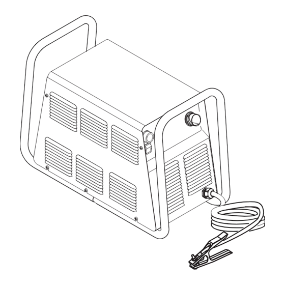
Thermal Dynamics CUTMASTER SL100SV Operating Manual (172 pages)
AUTOMATED PLASMA CUTTING SYSTEM
Brand: Thermal Dynamics
|
Category: Welding System
|
Size: 3 MB
Table of Contents
Advertisement

Thermal Dynamics CUTMASTER SL100SV Operating Manual (172 pages)
AUTOMATED PLASMA CUTTING SYSTEM
Brand: Thermal Dynamics
|
Category: Welding System
|
Size: 13 MB