Concept2 dynamic Assembly Manual
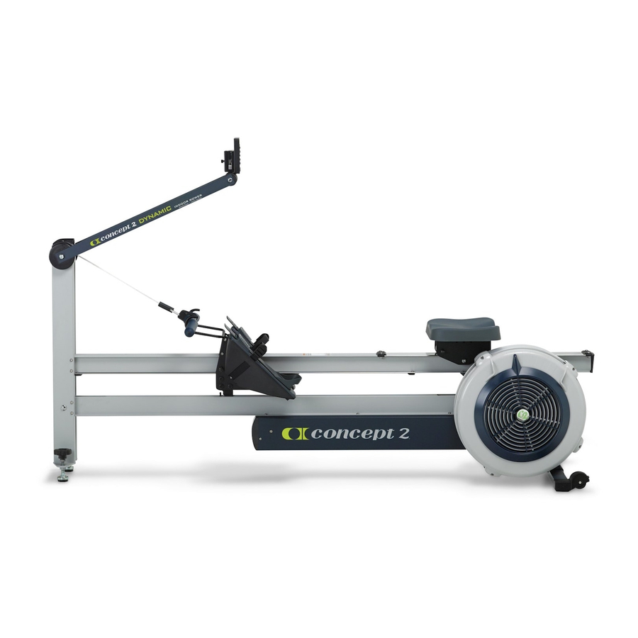
Dynamic
indoor rower
Hide thumbs
Also See for dynamic:
- Unpacking and assembly instructions (8 pages) ,
- Quick start manual (3 pages) ,
- User manual
Advertisement
Quick Links
Advertisement

Related Manuals for Concept2 dynamic


Summary of Contents for Concept2 dynamic
- Page 1 UNPACKING AND ASSEMBLY dynamic indoor rower...
-
Page 2: Assembly Instructions
CONCEPT2 DYNAMIC INDOOR ROWER Assembly Instructions Step 1. Open the two boxes and remove all the parts. Lay out the parts as shown below and read through the assembly instructions before beginning assembly. Note: The clear plastic shield located on the top of the flywheel is the optional Wind Shield. See Additional Notes for usage on page 9... - Page 3 Assembly (2) 3/8” (.95 cm) PN 2239 Be sure that caster wheels point back, as shown in the photo of the assembled Dynamic Indoor Rower on page 9. Install the two screws and photo A tighten snugly. See photo A.
- Page 4 CONCEPT2 DYNAMIC INDOOR ROWER Assembly Instructions Start all three 3/8” screws through the flange of the shuttle channel into the corresponding threaded holes in the return mechanism box. Do not fully tighten the screws until all three screws are in place. See photo F.
- Page 5 CONCEPT2 DYNAMIC INDOOR ROWER Assembly continued Step 7: Install Rail Assembly End Stop (2) 1/2” (1.27 cm) PN 2226 Rail Assembly (1) x Rail Assembly end stop w/2 nuts Install the rail assembly end stop on the photo K underside of the rail assembly. Be sure nuts are Shuttle Channel oriented down toward the floor.
- Page 6 CONCEPT2 DYNAMIC INDOOR ROWER Assembly continued Feed it all the way through the rail assembly until it comes out the other end. See photo P. photo P Partially unwrap the white tape and wrap it around the generator cable plug, covering the plug.
- Page 7 CONCEPT2 DYNAMIC INDOOR ROWER Assembly continued At the opposite end of the machine where the shuttle channel meets the rear leg, reach into the slot in the shuttle channel and grasp the shuttle. Pull the shuttle up through the slot in the shuttle channel so that it is exposed.
- Page 8 CONCEPT2 DYNAMIC INDOOR ROWER Assembly continued Step 11: Install Handle Drive Cord and Top Pulley Front Leg End Cap (2) 1 3/8” (3.49 cm) PN 2228 Run the handle with drive cord around the top pulley. See photo Z. photo Z...
-
Page 9: Additional Notes
We therefore view the lower tension that can be achieved with this design as a positive feature. The tension is set low when we ship the Dynamic Indoor Rower and we suggest rowing with it like this for a while before choosing to tightening the bungee if you really want it to feel “more like an erg.”... - Page 10 CONCEPT2 DYNAMIC INDOOR ROWER Front Leg/ Monitor Arm Assembly Foot Carriage Wind Shield Rail Assembly Shuttle Channel Caster Wheel Front Foot Flywheel Leveling Screws Page 10 0914 CONCEPT2.COM...
Need help?
Do you have a question about the dynamic and is the answer not in the manual?
Questions and answers