Concept2 Dynamic Unpacking And Assembly Instructions
Hide thumbs
Also See for Dynamic:
- Assembly manual (10 pages) ,
- Quick start manual (3 pages) ,
- User manual
Advertisement
Quick Links
Advertisement

Related Manuals for Concept2 Dynamic


Summary of Contents for Concept2 Dynamic
- Page 1 UNPACKING AND ASSEMBLY...
-
Page 2: Parts For Assembly
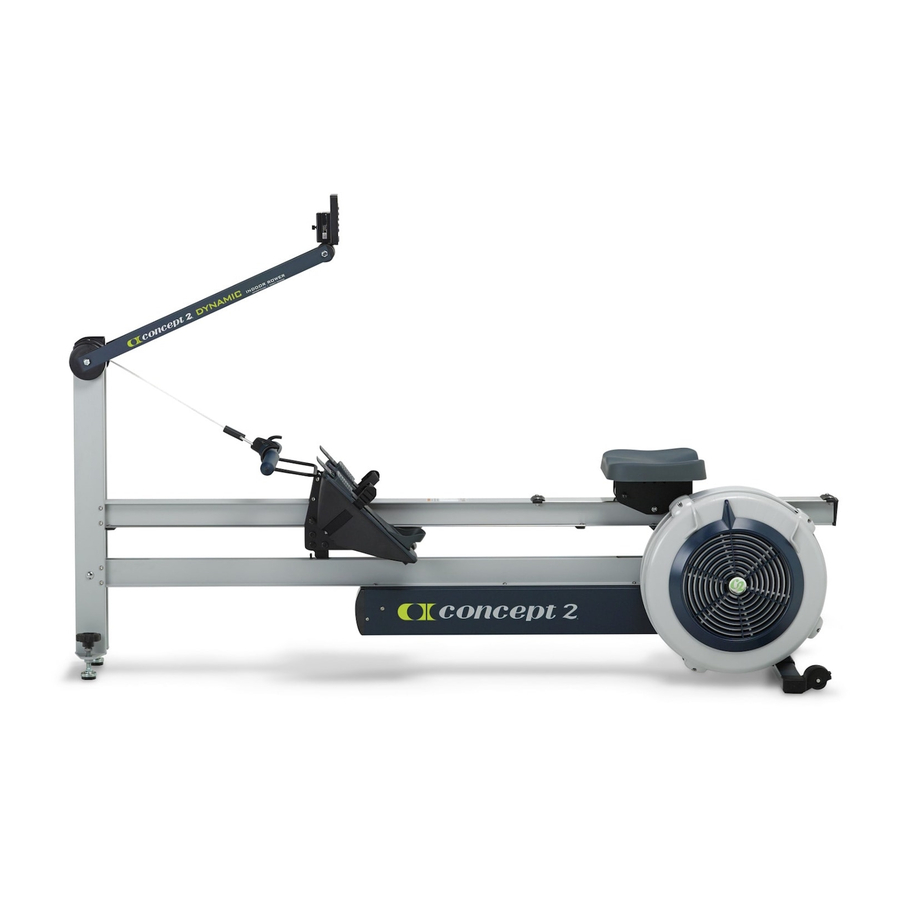
CONCEPT2 DYNAMIC INDOOR ROWER Assembly Instructions Step 1. Open the two boxes and remove all the parts. Lay out the parts as shown below and read through the assembly instructions before beginning assembly. Flywheel Return Assembly Foot Carriage Handle Rail Assembly... - Page 3 Step 2: Attach Rear Foot to Flywheel Box Assembly (2) 3/8” (.95 cm) PN 2239 Be sure that caster wheels point back, as shown in the photo of the assembled Dynamic Indoor Rower on page 8. Install the two screws and tighten photo A snugly. See photo A.
- Page 4 CONCEPT2 DYNAMIC INDOOR ROWER Assembly continued Start all three 3/8” screws through the flange of the shuttle channel into the corresponding threaded holes in the return mechanism box. Do not fully tighten the screws until all three screws are in place. See photo F.
- Page 5 CONCEPT2 DYNAMIC INDOOR ROWER Assembly continued Pull the handle all the way out (away from the flywheel) so that the drive cord is stretched out straight in the shuttle channel. This action will cause the foot carriage to move toward the flywheel.
- Page 6 CONCEPT2 DYNAMIC INDOOR ROWER Assembly continued Step 9: Install the Generator Cable Uncoil the black installation leader tape by removing the blue tape. DO NOT remove the white tape on the end. At the back end of the shuttle channel near the...
- Page 7 CONCEPT2 DYNAMIC INDOOR ROWER Assembly continued Step 10: Install Handle Drive Cord and Front Leg End Cap Top Pulley (2) 1 3/8” (3.49 cm) PN 2228 Run the handle with drive cord around the top pulley. See photo U. photo U...
-
Page 8: Additional Notes
We therefore view the lower tension that can be achieved with this design as a positive feature. The tension is set low when we ship the Dynamic Indoor Rower and we suggest rowing with it like this for a while before choosing to tightening the bungee if you really want it to feel “more like an erg.”...
Need help?
Do you have a question about the Dynamic and is the answer not in the manual?
Questions and answers