
Subscribe to Our Youtube Channel
Related Manuals for IEI Technology DM-F17A/PC-R31


Summary of Contents for IEI Technology DM-F17A/PC-R31
- Page 1 DM-F S e rie s Mo n ito r DM Series Industrial Monitor MODEL: DM-F S e rie s 12”~24” LCD Mo n ito r Dis p la yP o rt/HDMI/VGA, IP 65 P ro te c tio n , Ro HS Us e r Ma n u a l P a g e I Re v.
- Page 2 DM-F S e rie s Mo n ito r Re vis io n Date Version Changes Update Figure 3-1: 3-pin Terminal Block 29 April, 2015 1.12 Update Section 1.6: Technical Specifications 4 March, 2015 1.11 Update Section 1.8: Physical Dimensions Update Section 3.4.1: Panel Mounting (Cutout dimensions also updated) Update to R11 version...
- Page 3 DM-F S e rie s Mo n ito r Co p yrig h t COP YRIGHT NOTICE The information in this document is subject to change without prior notice in order to improve reliability, design and function and does not represent a commitment on the part of the manufacturer.
-
Page 4: Table Of Contents
DM-F S e rie s Mo n ito r Ta b le o f Co n te n ts 1 INTRODUCTION ......................1 1.1 O ........................2 VERVIEW 1.2 F ........................2 EATURES 1.3 M ....................3 ODEL ARIATIONS 1.4 A ...................... - Page 5 DM-F S e rie s Mo n ito r 3.3.4 HDMI Connector ..................... 23 3.3.5 RS-232 for Touch Panel Connector (Reserved for resistive touch ATO) ..23 3.3.6 USB for Touch Panel Connector ..............24 3.3.7 VGA Connector ....................24 3.4 M ..................
- Page 6 DM-F S e rie s Mo n ito r A.2.2 Cleaning Tools ....................59 B CERTIFICATIONS ....................60 B.1 R HS C ....................61 OMPLIANT B.2 IP 65 C ................61 OMPLIANT RONT ANEL C SMARTOSD ........................ 62 C.1 IEI OSD Q ............
- Page 7 DM-F S e rie s Mo n ito r Lis t o f Fig u re s Figure 1-1: DM-F Series ......................... 2 Figure 1-2: Typical Monitor Front View ..................4 Figure 1-3: Typical Rear View ......................5 Figure 1-4: Connectors (DM-F12A/15A/17A) ................6 Figure 1-5: Connectors (DM-F22A/24A) ..................
- Page 8 DM-F S e rie s Mo n ito r Figure 3-21: Bolt Dimensions ......................30 Figure 3-22: Steering Button Dimensions ..................30 Figure 3-23: The Rack/Cabinet Bracket ..................31 Figure 3-24: Secure the Rack/Cabinet Bracket ................32 Figure 3-25: Install into a Rack/Cabinet ..................32 Figure 3-26: Wall-mounting Bracket ...................33 Figure 3-27: Mount the Chassis ....................34 Figure 3-28: VESA Mounting Holes ....................35...
- Page 9 DM-F S e rie s Mo n ito r Lis t o f Ta b le s Table 1-1: DM-F Series Model Variations ..................3 Table 1-2: DM-F Series Specifications ..................8 Table 2-1: Packing List .........................16 Table 2-2: Optional Items ......................17 Table 3-1: HDMI Connector Pinouts ...................23 Table 4-1: OSD Menu Structure ....................40 Table C-1: SmartOSD Menu Structure ..................68...
-
Page 10: Introduction
DM-F S e rie s Mo n ito r Ch a p te r In tro d u c tio n P a g e 1... -
Page 11: Overview
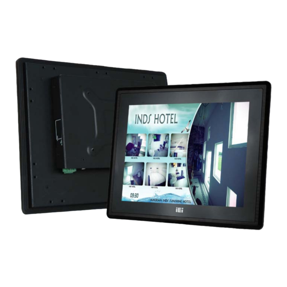
DM-F S e rie s Mo n ito r 1.1 Ove rvie w Figure 1-1: DM-F Series The DM-F series LCD monitor is the latest member of IEI’s line of sophisticated LCD designs, and it has been improved to be RoHS compliant. It is designed to fit industrial automation, or any other applications that require minimum installation space and flexible configuration. -
Page 12: Model Variations
DM-F S e rie s Mo n ito r 1.3 Mo d e l Va ria tio n s The DM-F series LCD monitor base models have a variety of variants. The model variations are listed in Table 1-1. Model Number Touch Screen DM-F12A/R-R10 W/ USB resistive touch screen... -
Page 13: External Overview
DM-F S e rie s Mo n ito r Full-service receptionist kiosk Hospital self-registration terminal Interactive photo kiosk Video rental kiosk Self-service POS terminal 1.5 Exte rn a l Ove rview The DM-F series LCD monitors are durable devices that can be used in harsh industrial environments. -
Page 14: Rear View
DM-F S e rie s Mo n ito r 1.5.2 Re a r Vie w The rear panel provides access to retention screw holes that support various mounting. There is a 7-key membrane OSD keypad on the rear panel. Figure 1-3 shows a typical DM-F rear panel. Figure 1-3: Typical Rear View P a g e 5... -
Page 15: Connectors
DM-F S e rie s Mo n ito r 1.5.3 Co n n e c to rs Figure 1-4 and Figure 1-5 shows the bottom panel of the DM-F series LCD monitor. All connectors are fully described in Section 3.3. Figure 1-4: Connectors (DM-F12A/15A/17A) Figure 1-5: Connectors (DM-F22A/24A) P a g e 6... -
Page 16: Technical Specifications
DM-F S e rie s Mo n ito r 1.6 Te c h n ic a l Sp e c ific a tio n s Table 1-2 shows the DM-F series technical specifications. Model DM-F12A DM-F15A DM-F17A DM-F22A DM-F24A LCD Display 12"... -
Page 17: Certifications
DM-F S e rie s Mo n ito r Model DM-F12A DM-F15A DM-F17A DM-F22A DM-F24A Weight (Net/Gross) 2.7/4.9 3.5/5.5 4.4/7.1 6.3/9.6 7.6/10.9 Operating -20°C ~ 60°C (with air flow) -10°C ~ 50°C (with air flow) Temperature Storage -20°C ~ 70°C -20°C ~ 60°C Temperature Humidity... -
Page 18: Physical Dimensions
DM-F S e rie s Mo n ito r 1.8 P h ys ic a l Dim e n s io n s The following sections describe the physical dimensions for each model of the DM-F series LCD monitor. 1.8.1 DM-F12A P h ys ic a l Dim e n s io n s The physical dimensions of the DM-F12A are shown in Figure 1-6. -
Page 19: Dm-F15A Physical Dimensions
DM-F S e rie s Mo n ito r 1.8.2 DM-F15A P h ys ic a l Dim e n s io n s The physical dimensions of the DM-F15A are shown in Figure 1-7. Figure 1-7: DM-F15A Physical Dimensions (millimeters) P a g e 10... -
Page 20: Dm-F17A Physical Dimensions
DM-F S e rie s Mo n ito r 1.8.3 DM-F17A P h ys ic a l Dim e n s io n s The physical dimensions of the DM-F17A are shown in Figure 1-8. Figure 1-8: DM-F17A Physical Dimensions (millimeters) P a g e 11... -
Page 21: Dm-F22A Physical Dimensions
DM-F S e rie s Mo n ito r 1.8.4 DM-F22A P h ys ic a l Dim e n s io n s The physical dimensions of the DM-F22A are shown in Figure 1-9. Figure 1-9: DM-F22A Physical Dimensions (millimeters) P a g e 12... -
Page 22: Dm-F24A Physical Dimensions
DM-F S e rie s Mo n ito r 1.8.5 DM-F24A P h ys ic a l Dim e n s io n s The physical dimensions of the DM-F24A are shown in Figure 1-10. Figure 1-10: DM-F24A Physical Dimensions (millimeters) P a g e 13... -
Page 23: Unpacking
DM-F S e rie s Mo n ito r Chapter Un p a c kin g P a g e 14... -
Page 24: Unpacking Procedure
DM-F S e rie s Mo n ito r 2.1 Un pa c kin g P ro c e du re To unpack the DM-F series LCD monitor, follow the steps below: WARNING: The front side LCD screen has a protective plastic cover stuck to the screen. -
Page 25: Packing List
DM-F S e rie s Mo n ito r 2.2 P a c kin g Lis t The DM-F series monitor is shipped with the following components: Qu a n tity Ite m Im a g e DM-F series USB Cable (For touch screen) (P/N: 32001-006100-100-RS) VGA Cable (P/N: 32000-036200-RS) -
Page 26: Optional Items
DM-F S e rie s Mo n ito r 2.3 Op tio n a l Ite m s The following items are optional accessories for the DM-F series monitor: Ite m DM-F12A DM-F15A DM-F17A DM-F22A DM-F24A ARM-11-RS ARM-31-RS Stand STAND-A19-RS STAND-C19-RS STAND-A12-RS STAND-B19-RS... -
Page 27: Installation
DM-F S e rie s Mo n ito r Ch a p te r In s ta lla tio n P a g e 18... -
Page 28: Installation Precautions
DM-F S e rie s Mo n ito r 3.1 In s ta lla tio n P re c a u tio n s When installing the DM-F series LCD monitor, please follow the precautions listed below: Read the user manual: The user manual provides a complete description of the DM-F series LCD monitor, installation instructions and configuration options. -
Page 29: Pre - Installation Preparation
DM-F S e rie s Mo n ito r 3.2 P re -in s ta lla tio n P re pa ra tio n 3.2.1 To o ls Before installing the DM-F series LCD monitor, make sure the following tools are on hand: ... -
Page 30: Displayport Connector
DM-F S e rie s Mo n ito r Figure 3-1: Connectors (DM-F12A/15A/17A) Figure 3-2: Connectors (DM-F22A/24A) 3.3.1 Dis p la yP o rt Co n n e c to r The DisplayPort connector transmits a digital signal to compatible DisplayPort display devices such as a TV or computer screen. -
Page 31: 36V Terminal Block
DM-F S e rie s Mo n ito r C_DDI0_DP_AUXN C_DDI0_DP_HPD Table 3-1: Display Port Connector Pinouts Figure 3-3: DisplayPort connector 3.3.2 9V-36V Te rm ina l Blo c k Connect the leads of 9V-36V DC power supply into the terminal block. Make sure that the power and ground wires are attached to the correct sockets of the connector. -
Page 32: Hdmi Connector
DM-F S e rie s Mo n ito r Figure 3-5: 9V-36V DC Jack 3.3.4 HDMI Co n n e c to r The HDMI connector connects to a display device with HDMI interface. DESCRIPTION DESCRIPTION HDMI_TMDS_C_DATA2 HDMI_TMDS_C_DATA2# HDMI_TMDS_C_DATA1 HDMI_TMDS_C_DATA1# HDMI_TMDS_C_DATA0 HDMI_TMDS_C_DATA0# HDMI_TMDS_C_CLK... -
Page 33: Usb For Touch Panel Connector
DM-F S e rie s Mo n ito r DESCRIPTION DESCRIPTION NDSR NRTS NDTR Table 3-3: RS-232 Touch Panel Connector Pinouts Figure 3-7: RS-232 Touch Panel Connector 3.3.6 US B fo r To u c h P a ne l Co n n e c to r Use the rear panel standard USB touch panel connector to connect the monitor to the system graphics interface. -
Page 34: Mounting The Monitor
DM-F S e rie s Mo n ito r DESCRIPTION DESCRIPTION DESCRIPTION GROUND GREEN GROUND DDCDAT BLUE GROUND HSYNC VSYNC GROUND GROUND DDCCLK Table 3-5: VGA Connector Pinouts Figure 3-9: VGA Connector 3.4 Mo u n tin g th e Mo n ito r The DM-F series LCD monitor can be mounted in a panel, cabinet, rack or wall. -
Page 35: Figure 3-10: Mounting Clamps Holder
DM-F S e rie s Mo n ito r Mo d e l Mo u n tin g Cla m p s (Ho ld e rs in c lu d e d ) DM-F12A DM-F15A DM-F17A DM-F22A DM-F24A Table 3-6: Panel Mounting Clamps Figure 3-10: Mounting Clamps Holder Figure 3-11: Mounting Clamps To mount the DM-F series LCD monitor into a panel, please follow the steps below. -
Page 36: Figure 3-12: Dm-F12A Cutout Dimensions (Unit: Mm)
DM-F S e rie s Mo n ito r Figure 3-12: DM-F12A Cutout Dimensions (Unit: mm) Figure 3-13: DM-F15A Cutout Dimensions (Unit: mm) Figure 3-14: DM-F17A Cutout Dimensions (Unit: mm) Figure 3-15: DM-F22A Cutout Dimensions (Unit: mm) P a g e 27... -
Page 37: Figure 3-16: Dm-F24A Cutout Dimensions (Unit: Mm)
DM-F S e rie s Mo n ito r Figure 3-16: DM-F24A Cutout Dimensions (Unit: mm) Secure the mounting clamps holders to the corresponding holes on the rear of S te p 3: the monitor. Figure 3-17: Secure the Mounting Clamps Holders Slide the monitor through the hole until the aluminum frame is flush against the S te p 4: panel. -
Page 38: Figure 3-18: Panel Mounting Clamp Position
DM-F S e rie s Mo n ito r Figure 3-18: Panel Mounting Clamp Position S te p 6: Tighten the screws that pass through the panel mounting clamps until the plastic caps at the front of all the screws are firmly secured to the panel. Figure 3-19: Mounting Clamps Holder Dimensions P a g e 29... -
Page 39: Figure 3-20: Ultra Set Plate Dimensions
DM-F S e rie s Mo n ito r Figure 3-20: Ultra Set Plate Dimensions Figure 3-21: Bolt Dimensions Figure 3-22: Steering Button Dimensions P a g e 30... -
Page 40: Cabinet And Rack Installation
DM-F S e rie s Mo n ito r 3.4.2 Ca b in e t a n d Ra c k Ins ta lla tio n The DM-F series LCD monitor can be installed into a cabinet or rack. The installation procedures are similar to the panel mounting installation. -
Page 41: Figure 3-24: Secure The Rack/Cabinet Bracket
DM-F S e rie s Mo n ito r Figure 3-24: Secure the Rack/Cabinet Bracket S te p 4: Slide the LCD monitor with the attached rack/cabinet bracket into a rack or cabinet (Figure 3-25). Figure 3-25: Install into a Rack/Cabinet Once the LCD monitor with the attached rack/cabinet bracket has been properly S te p 5: inserted into the rack or cabinet, secure the front of the rack/cabinet bracket to... -
Page 42: Wall Mounting
DM-F S e rie s Mo n ito r 3.4.3 Wa ll Mo u n tin g CAUTION: Due to safety concerns, it is highly recommended to use the VESA mounting kits provided by IEI for wall, stand and arm mounting. If the VESA mounting kit is purchased separately, please make sure the mounting kit is UL-listed. -
Page 43: Figure 3-27: Mount The Chassis
DM-F S e rie s Mo n ito r S te p 11: Insert the four monitor mounting screws provided in the wall mounting kit into the four screw holes on the real panel of the monitor and tighten until the screw shank is secured against the rear panel (Figure 3-27). -
Page 44: Monitor Stand Installation
DM-F S e rie s Mo n ito r 3.4.4 Mo n ito r Sta n d In s ta lla tio n The DM-F series LCD monitor has Video Electronics Standards Association (VESA) standard mounting holes tapped into the rear panel. The standard holes are M4 set at 100m x 100mm apart (Figure 3-28). -
Page 45: Monitor Arm Installation
DM-F S e rie s Mo n ito r Figure 3-29: Monitor Stand Mounting 3.4.5 Mo n ito r Arm In s ta lla tio n The DM-F series LCD monitor has Video Electronics Standards Association (VESA) standard mounting holes tapped into the rear panel. The standard holes are M4 set at 100m x 100mm apart (Figure 3-28). -
Page 46: Figure 3-30: Monitor Arm Mounting
DM-F S e rie s Mo n ito r Figure 3-30: Monitor Arm Mounting P a g e 37... -
Page 47: On-Screen-Display (Osd) Controls
DM-F S e rie s Mo n ito r Ch a p te r On -S c re e n -Dis p la y (OS D) Co n tro ls P a g e 38... -
Page 48: User Mode Osd Structure
DM-F S e rie s Mo n ito r 4.1 Us e r Mo d e OS D Stru c tu re 4.1.1 OS D Ke ypa d There are several on-screen-display (OSD) control buttons of the OSD keypad on the monitor rear panel. -
Page 49: Osd Menu Structure
DM-F S e rie s Mo n ito r 4.1.2 OS D Me n u Stru c tu re Table 4-1 shows the OSD menu structure for all models of the DM-F series LCD monitor. Level 0 Level 1 Level 2 Value Image Brightness... -
Page 50: Using The Osd
DM-F S e rie s Mo n ito r 4.2 Us in g th e OS D OSD menu options are described below. 4.2.1 Im a g e Me n u Image menu features are shown in Figure 4-2. Figure 4-2: Image Menu The brightness option adjusts the brightness of screen. -
Page 51: Display Menu
DM-F S e rie s Mo n ito r Figure 4-3: Color Settings Automatically adjusts the color settings. auto This item allows adjustment of the following items. Color temp 5000k – NTSC standard Kelvin 6500k – NTSC standard Kelvin ... -
Page 52: System Menu
DM-F S e rie s Mo n ito r Figure 4-4: Display Menu Automatically adjusts the LCD screen position. Auto Adjust Phase Adjusts the input signal (Analog only) Adjusts the dot clock position Clock Display Position Adjusts the horizontal and vertical position of the display screen Display Mode This item allows adjustment of the Gamma. -
Page 53: Input
DM-F S e rie s Mo n ito r Figure 4-5: System Menu Input Allows selection of input device to use. (Figure 4-6) OSD Settings Provides options for OSD configuration. (Figure 4-7) Provides information on the LCD monitor, such as firmware version, Information release date and input resolution. -
Page 54: Figure 4-6: Input Options
DM-F S e rie s Mo n ito r Figure 4-6: Input Options Input options are described below. Display Port This item sets the input device to display port. This item sets the input device to VGA. This item sets the input device to HDMI. HDMI autoscan Selects the input device to use automatically. -
Page 55: Osd Settings
DM-F S e rie s Mo n ito r 4.2.3.2 OS D S e ttin g s The OSD settings are shown in Figure 4-7. Figure 4-7: OSD Settings Menu OSD settings are described below. Determines how many seconds the OSD screen stays on screen Timer before it disappears when OSD is left unattended. -
Page 56: Software Drivers
DM-F S e rie s Mo n ito r Ch a p te r S o ftwa re Drive rs P a g e 47... -
Page 57: Introduction
DM-F S e rie s Mo n ito r 5.1 In tro d u c tio n The touch panel controller enables analog resistive touch panels for four-wire, five-wire & eight-wire models. The controller directly communicates with the PC system through the touch panel communications interface. -
Page 58: Touch Panel Driver Installation
DM-F S e rie s Mo n ito r The default touch screen interface for the DM-F series monitor is USB interface. The RS-232 interface is only reserved for resistive touch ATO RS-232 Interface: If the touch screen interface connection is an RS-232 connection, connect the RS-232 connector on the single board computer to the DB-9 connector of the DM-F series monitor. -
Page 59: Figure 5-1: Setup Icon
DM-F S e rie s Mo n ito r Figure 5-1: Setup Icon S te p 4: Double click the setup icon in Figure 5-1. The Welcome screen in Figure 5-2 appears. S te p 5: Figure 5-2: Welcome Screen Click Next to continue. -
Page 60: Figure 5-3: License Agreement
DM-F S e rie s Mo n ito r Figure 5-3: License Agreement S te p 8: The installation destination screen appears. See Figure 5-4. Click Install. Figure 5-4: Initiate Install The installation of the program begins. See Figure 5-5. S te p 9: P a g e 51... -
Page 61: Figure 5-5: Installation Starts
DM-F S e rie s Mo n ito r Figure 5-5: Installation Starts S te p 10: When the installation is complete, the complete screen appears. See Figure 5-6. To complete the installation process click Finish. Figure 5-6: Finish Installation P a g e 52... -
Page 62: Change The Touch Screen Interface
DM-F S e rie s Mo n ito r 5.4 Ch a n g e th e To u c h S c re e n In te rfa c e If the touch screen interface must be changed from an RS-232 interface to a USB interface or, from a USB interface to an RS-232 interface, the following steps must be followed. -
Page 63: Figure 5-8: Penmount Monitor Popup Menu
DM-F S e rie s Mo n ito r Figure 5-8: PenMount Monitor Popup Menu Click Control Panel in the pop up menu shown in Figure 5-8. S te p 5: S te p 6: The configuration screen in Figure 5-9 appears. Figure 5-9: Configuration Screen S te p 7: Double click the PenMount 6000 icon as shown in Figure 5-9. -
Page 64: Figure 5-10: Calibration Initiation Screen
DM-F S e rie s Mo n ito r Figure 5-10: Calibration Initiation Screen The calibration screen in is shown. See Figure 5-11. S te p 10: Figure 5-11: Calibration Screen S te p 11: Follow the instructions. The user is asked touch the screen at five specified points after which the screen is calibrated. -
Page 65: A Safety Precautions
DM-F S e rie s Mo n ito r Ap p e n d ix S a fe ty P re c a u tio n s P a g e 56... -
Page 66: Safety Precautions
DM-F S e rie s Mo n ito r WARNING: The precautions outlined in this chapter should be strictly followed. Failure to follow these precautions may result in permanent damage to the DM-F Series. A.1 S a fe ty P re c a u tio n s Please follow the safety precautions outlined in the sections that follow: A.1.1 Ge n e ra l S a fe ty P re c a u tio n s Please ensure the following safety precautions are adhered to at all times. -
Page 67: Anti-Static Precautions
DM-F S e rie s Mo n ito r A.1.2 An ti-s ta tic P re c a u tio n s WARNING: Failure to take ESD precautions during the installation of the DM-F Series may result in permanent damage to the DM-F Series and severe injury to the user. -
Page 68: Cleaning Tools
DM-F S e rie s Mo n ito r The interior of the DM-F Series does not require cleaning. Keep fluids away from the DM-F Series interior. Be cautious of all small removable components when vacuuming the DM-F Series. -
Page 69: B Certifications
DM-F S e rie s Mo n ito r Ap p e n d ix Ce rtific a tio n s P a g e 60... -
Page 70: R Ohs Compliant
DM-F S e rie s Mo n ito r B.1 Ro HS Co m p lia n t All models in the DM-F LCD monitor series comply with the Restriction of Hazardous Materials (RoHS) Directive. This means that all components used to build the industrial workstations and the workstation itself are RoHS compliant. -
Page 71: C Smartosd
DM-F S e rie s Mo n ito r Ap p e n d ix s m a rtOS D P a g e 62... -
Page 72: Iei Smart Osd Quick Installation Guide
DM-F S e rie s Mo n ito r C.1 IEI s m a rtOS D Qu ic k In s ta lla tio n Gu id e IEI smartOSD is a proprietary On-Screen-Display (OSD) software solution from IEI that enables easy, remote monitor setting adjustments in a Windows environment. - Page 73 DM-F S e rie s Mo n ito r Figure C-1: smartOSD Welcome Screen S te p 4: Click Next to continue. The Folder Select screen in Figure C-2 appears. S te p 5: Figure C-2: smartOSD Folder Select Screen Select the installation folder in Figure C-2 shown above.
- Page 74 DM-F S e rie s Mo n ito r Figure C-3: smartOSD Confirm Installation S te p 9: Confirm the installation by clicking Next in the screen above. S te p 10: The program starts to install and the progress bar shown in FIgure C-4 appears. Figure C-4: smartOSD Installation Progress S te p 11: When the installation is complete the “Complete Installation”...
-
Page 75: Software Illustration
DM-F S e rie s Mo n ito r Figure C-5: smartOSD Installation Complete S te p 12: Click Close in the screen above. S te p 13: After quick setup is complete, the IEI smartOSD wizard logo appears on the desktop as shown in the screen below. - Page 76 DM-F S e rie s Mo n ito r NOTE: To update the display setting status immediately, push the refresh button on every page To turn the system on, press ALT + P. Ite m Ele m e n ts Management Save/Load File Power Management...
-
Page 77: Table C-1: Smartosd Menu Structure
DM-F S e rie s Mo n ito r Auto Brightness (disabled in the DM-F Series) Main Source Input (YPbPr, S-Video and CVBS disabled) Volume (disabled in the DM-F Series) Factory Presets/OSD Lock/OSD Unlock Mute (disabled in the DM-F Series) Table C-1: SmartOSD Menu Structure P a g e 68... -
Page 78: Manage Page
DM-F S e rie s Mo n ito r C.4.1 Ma n a g e P a g e Figure C-6: Manage Page P a g e 69... -
Page 79: Edid Page
DM-F S e rie s Mo n ito r C.4.2 EDID P a g e Figure C-7: EDID Page P a g e 70... -
Page 80: Image Page
DM-F S e rie s Mo n ito r C.4.3 Im a g e P a g e Figure C-8: Image Page P a g e 71... -
Page 81: Display Page (For Analog Signal)
DM-F S e rie s Mo n ito r C.4.4 Dis p la y P a g e (fo r a n a lo g s ig n a l) Figure C-9: Display Page P a g e 72... -
Page 82: Color Page
DM-F S e rie s Mo n ito r C.4.5 Co lo r P a g e Figure C-10: Color Page P a g e 73... -
Page 83: Pip Page
DM-F S e rie s Mo n ito r C.4.6 P IP P a ge NOTE: The functions in the PIP page are only available in the MLCD-KIT Series and AFOLUX Series monitors. Figure C-11: PIP Page P a g e 74... -
Page 84: System Page
DM-F S e rie s Mo n ito r C.4.7 S ys te m P a g e Figure C-12: System Page NOTE: Some of the functions in the System Page are only available to some of the IEI LCD series as following: ... -
Page 85: About Page
DM-F S e rie s Mo n ito r C.4.8 Ab o u t P a g e Figure C-13: About Page P a g e 76... -
Page 86: Smart Osd Faq
DM-F S e rie s Mo n ito r C.5 s m a rtOS D FAQ For troubleshooting, please see the steps below: C.5.1 Win d ows 2000 In s ta lla tio n Fa ilu re Installation fails under Windows 2000 and shows the following image: Figure C-14: DLL Missing Solution: Download and install service pack Windows Installer 3.1 C.5.2 Vis ta In s ta lla tio n Fa ilu re... -
Page 87: Model Failure
DM-F S e rie s Mo n ito r Solution: Install SmartOSD.exe as the administrator authority Figure C-16: Install as Administrator C.5.3 Mo d e l Fa ilu re The Model Fail error message shown below appears. Figure C-17: Firmware Incompatibility Solution: SmartOSD only supports firmware version 2.0 and following versions. -
Page 88: Ddc Port Failure
DM-F S e rie s Mo n ito r C.5.4 DDC P o rt Fa ilu re The DDC port fail error message shown below appears. Figure C-18: DDC Port Failure Solutions: Check VGA or HDMI cable Check an IEI monitor is being used ...
Need help?
Do you have a question about the DM-F17A/PC-R31 and is the answer not in the manual?
Questions and answers