
Related Manuals for Thermal Dynamics CUTMASTER 81


Summary of Contents for Thermal Dynamics CUTMASTER 81
- Page 1 ™ CUTMASTER PLASMA CUTTING SYSTEM A-04517 Operating Manual Rev. AB.01 Date: March 14, 2007 Manual # 0-2956 Operating Features:...
- Page 2 YOU ARE IN GOOD COMPANY! The Brand of Choice for Contractors and Fabricators Worldwide. Thermal Dynamics is a Global Brand of manual and automation Plasma Cutting Products for Thermadyne Industries Inc. We distinguish ourselves from our competition through market- leading, dependable products that have stood the test of time.
- Page 3 Manufacturer assumes no liability for its use. Plasma Cutting Power Supply CutMaster™ 81 Operating Manual Number 0-2956 Covered under U.S. Patents. Published by: Thermal Dynamics Corporation 82 Benning Street West Lebanon, New Hampshire, USA 03784 (603) 298-5711 www.thermal-dynamics.com © Copyright 2003, 2004, 2005, 2006, 2007 by Thermal Dynamics Corporation All rights reserved.
-
Page 4: Table Of Contents
TABLE OF CONTENTS SECTION 1: GENERAL INFORMATION ....................1-1 1.01 Notes, Cautions and Warnings ..............1-1 1.02 Important Safety Precautions ............... 1-1 1.03 Publications ....................1-2 1.04 Declaration of Conformity ................1-4 1.05 Statement of Warranty .................. 1-5 SECTION 2: INTRODUCTION ....................... - Page 5 TABLE OF CONTENTS (continued) PATENT INFORMATION ......................6-4 APPENDIX 1: SEQUENCE OF OPERATION (BLOCK DIAGRAM) ......................A-1 APPENDIX 2: DATA TAG INFORMATION ................A-2 APPENDIX 3: MAINTENANCE SCHEDULE ................A-3 APPENDIX 4: TORCH PIN - OUT DIAGRAMS ................A-4 APPENDIX 5: TORCH CONNECTION DIAGRAMS ..............A-5 APPENDIX 6: SYSTEM SCHEMATIC, 208/230 VOLT UNITS ..........
-
Page 7: General Information
SECTION 1: GASES AND FUMES GENERAL INFORMATION Gases and fumes produced during the plasma cutting process can be dangerous and hazardous to your health. 1.01 Notes, Cautions and Warnings • Keep all fumes and gases from the breathing area. Throughout this manual, notes, cautions, and warnings Keep your head out of the welding fume plume. -
Page 8: Publications
• Wear dry gloves and clothing. Insulate yourself from the work piece or other parts of the welding PLASMA ARC RAYS circuit. • Repair or replace all worn or damaged parts. Plasma Arc Rays can injure your eyes and burn your skin. •... - Page 9 6. ANSI Standard Z49.2, FIRE PREVENTION IN THE USE OF CUTTING AND WELDING PROCESSES, obtain- able from American National Standards Institute, 1430 Broadway, New York, NY 10018 7. AWS Standard A6.0, WELDING AND CUTTING CONTAINERS WHICH HAVE HELD COMBUS- TIBLES, obtainable from American Welding Society, 550 N.W.
-
Page 10: Declaration Of Conformity
Rigorous testing is incorporated into the manufacturing process to ensure the manufactured product meets or exceeds all design specifications. Thermal Dynamics has been manufacturing products for more than 30 years, and will continue to achieve excellence in our area of manufacture. -
Page 11: Statement Of Warranty
Thermal Dynamics Corporation will honor warranty claims submitted within the warranty periods listed below. All warranty periods begin on the date of sale of the product to the original retail customer or 1 year after sale to an authorized Thermal Dynamics Distributor. - Page 12 This Page Intentionally Blank GENERAL INFORMATION Manual 0-2956...
-
Page 13: Introduction
This manual contains descriptions, operating instructions and basic maintenance procedures for the Thermal Dy- namics CutMaster 81 Plasma Cutting Power Supply only. Servicing of this equipment is restricted to properly trained personnel; unqualified personnel are strictly cautioned against attempting repairs or adjustments not cov- ered in this manual, at the risk of voiding the Warranty. -
Page 14: Input Wiring Specifications
24" 0.6 m 27.5 in / 696 mm 6" 12.4 in / 150 mm 315 mm A-03572 2.03 Input Wiring Specifications CutMaster 81 Input Wiring Requirements Input Power Input Current Input Suggested Sizes (See Notes) Voltage Freq. 1-Ph 3-Ph 1-Ph... -
Page 15: Power Supply Features
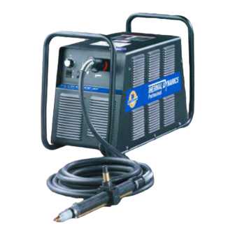
2.04 Power Supply Features Handle and Leads Wrap Control Panel Torch Leads Receptacle Art # A-04507 Work Cable and Clamp Gas Pressure Regulator / Filter Assembly Gas Inlet Port Ports for Optional Automation Interface Cable Gas Pressure Gauge Art # A-03738 Input Power Cord Manual 0-2956 INTRODUCTION... -
Page 16: Power Supply Options And Accessories
2.05 Power Supply Options and Accessories Section 6, Parts Lists, provides catalog numbers and ordering information. A. Single-Stage Air Filter Kit For use with compressed air shop systems. Filters moisture and particulate matter from the air stream to at least 0.85 microns. -
Page 17: Section 3: Installation
SECTION 3: INSTALLATION 3.01 Unpacking 1. Use the packing lists to identify and account for each item. 2. Inspect each item for possible shipping damage. If damage is evident, contact your distributor and / or shipping company before proceeding with the installation. 3. -
Page 18: Primary Input Power Connections
3.03 Primary Input Power Connections CAUTION Check your power source for correct voltage before plugging in or connecting the unit. The primary power source, fuse, and any extension cords used must conform to local electrical code and the recommended circuit protection and wiring requirements as specified in Section 2.03. - Page 19 C. Connections to 460 - Volt Single- Phase Power The 460 - Volt Power Supply will accept 460 - VAC, Single - Phase input power with a change of input power cable. 1. Remove the Power Supply cover per section 5.04. 2.
-
Page 20: Gas Connections
3.04 Gas Connections A. Connecting Air Supply to Unit Use only compressed air with this power supply. The connection is the same for compressed air from a compressor from high pressure cylinders. Refer to subsection 3.4-B or 3.4-C if an optional air line filter is to be installed. 1. - Page 21 B. Installing Optional Single - Stage Air Filter An optional filter kit is recommended for improved filtering with compressed air, to keep moisture and debris out of the torch. 1. Attach the Single - Stage Filter Hose to the Inlet Port. 2.
- Page 22 C. Installing Optional Two - Stage Air Filter Kit This optional two - stage air line filter is also for use on compressed air shop systems. Filter removes moisture and contaminants to at least 5 microns. Connect the air supply as follows: a.
- Page 23 D. Using High Pressure Air Cylinders When using high pressure air cylinders as the air supply: 1. Refer to the manufacturer’s specifications for installation and maintenance procedures for high pressure regula- tors. 2. Examine the cylinder valves to be sure they are clean and free of oil, grease or any foreign material. Briefly open each cylinder valve to blow out any dust which may be present.
-
Page 24: Torch Connections
3.05 Torch Connections If necessary, connect the torch to the Power Supply. Connect only the Thermal Dynamics model SL60 or SL100 Torch (with ATC connector) to this power supply. Maximum torch leads length is 100 feet / 30.5 m, including extensions. - Page 25 B. Check Air Quality To test the quality of air: 1. Put the ON / OFF switch in the ON (up) position. 2. Put the RUN / RAPID AUTO RESTART / SET switch in the SET (down) position. 3. Place a welding filter lens in front of the torch and turn on the air. Any oil or moisture in the air will be visible on the lens.
- Page 26 This Page Intentionally Blank INSTALLATION 3-10 Manual 0-2956...
-
Page 27: Section 4: Operation
SECTION 4: OPERATION 4.01 Product Features A. Front Panel Controls and Indicators A) Output Current Control AC Indicator Sets the desired output current. Output settings up Steady light indicates power supply is ready to 40 Amps may be used for drag cutting (with the for operation. -
Page 28: Preparations For Operating
Power Supply (60 amps maximum). Refer to the Torch Manual. B. Torch Connection Check that the torch is properly connected. Only Thermal Dynamics model SL60 or SL100 Torches may be connected to this Power Supply. C. Check Primary Input Power Source 1. - Page 29 F. Power On Place the Power Supply ON / OFF switch to the ON (up) position. AC indicator turns on. Gas indicator turns on if there is sufficient gas pressure for power supply operation. NOTE Minimum pressure for power supply operation is lower than minimum for torch operation. Art # A-03594 Manual 0-2956 OPERATION...
- Page 30 Art # A-03592 2. Adjust gas pressure per the gas settings chart. 65 - 80 psi / 4.5- 5.5 bar Pressure Control Knob / Bouton De Contrôle de Pression CutMaster 81 Gas Pressure Settings Leads SL60 SL100 (Hand Torch) (Machine Torch) Length...
- Page 31 H. Select Current Output Level 1. Place RUN / Rapid Auto Restart / SET to RUN (up) or Rapid Auto Restart (center) position. Gas flow stops. 2. Set the current output level, up to 40 amps for drag cutting (with the torch tip in contact with the workpiece), or up to 60 amps for standoff cutting.
- Page 32 K. Postflow Release the trigger to stop the cutting arc. Gas continues to flow for approximately 6 seconds. During post - flow, if the user moves the trigger release to the rear and presses the trigger, the pilot arc starts. The main arc transfers to the workpiece if the torch tip is within transfer distance to the workpiece.
-
Page 33: Service
SECTION 5: SERVICE 5.01 General Maintenance A. O-Ring Lubrication An o-ring on the Torch ATC Male Connector requires lubrication on on a regular basis, depending on how fre- quently the torch is disconnected and re-connected. This will allow the o-ring to remain pliable and provide a proper seal. - Page 34 B. Filter Element Replacement The Regulator/Filter Assembly is on the rear panel. For better system performance, the Regulator/Filter Assembly filter element should be checked per the Maintenance Schedule (Appendix 3), and either cleaned or replaced. Remove power from the power supply; turn off the gas supply and bleed down the system. Unscrew the bowl on the bottom of the Regulator/Filter Assembly.
- Page 35 C. Optional Single-Stage Filter Element Replacement These instructions apply to power supplies where the optional Single-Stage Filter has been installed. The Power Supply shuts down automatically when the Filter Element becomes completely saturated. The Filter Element can be removed from its housing, dried, and reused. Allow 24 hours for Element to dry. Refer to Section 6, Parts List, for replacement filter element catalog number.
- Page 36 D. Optional Two-Stage Filter Element Replacement The Two-Stage Air Filter has two Filter Elements. When the Filter Elements become dirty the Power Supply will continue to operate but cut quality may become unacceptable. Refer to Section 6, Parts List, for replacement filter element catalog number.
-
Page 37: Common Faults
Cutting speed too slow b. Torch standoff too high from workpiece c. Worn torch parts d. Improper cutting current e. Non - Genuine Thermal Dynamics parts used Incorrect gas pressure 4. Short Torch Parts Life a. Oil or moisture in air source b. -
Page 38: Basic Troubleshooting Guide
5.03 Basic Troubleshooting Guide WARNING There are extremely dangerous voltage and power levels present inside this unit. Do not attempt to diagnose or repair unless you have had training in power electronics measurement and troubleshooting techniques. A. Basic Troubleshooting: Overview This guide covers basic troubleshooting. - Page 39 6. Unit internal fuse blown or loose a. If blown, double-check input voltage and replace fuse per Section 5.04-C. If fuse blows again, return unit to an authorized service center. 7. Actual input voltage does not correspond to voltage of unit a.
- Page 40 G. Torch will not pilot; no gas flow; AC indicator ON, GAS indicator ON, DC indicator 1. Starter cartridge missing from torch a. Shut off power supply. Remove shield cup, install starter cartridge. Reinstall torch tip and shield cup. Turn power supply ON / OFF switch to ON (up).
- Page 41 I. Torch cannot be activated; AC indicator flashing; Gas indicator ON; Temp indicator OFF; DC indicator 1. System is in protective interlock mode. (User held torch trigger while turning on ON / OFF switch.) a. Release torch trigger. 2. System is in protective interlock mode. (Torch parts are missing or loose.) a.
- Page 42 6. Excessive oil or moisture in torch a. Put RUN / RAPID AUTO RESTART / SET switch in SET (down) position. Hold torch 1/8 inch (3 mm) from clean surface while purging and observe oil or moisture buildup (do not activate torch). If there are contami- nants in the gas, additional filtering may be needed.
-
Page 43: Power Supply Basic Parts Replacement
5.04 Power Supply Basic Parts Replacement WARNING Disconnect primary power to the system before disassembling the torch, leads, or power supply. This section describes procedures for basic parts replacement. For more detailed parts replacement procedures, refer to the Power Supply Service Manual. A. - Page 44 B. Cover Installation Reconnect the ground wire, if necessary. 2. Place the cover onto the power supply so that slots in the bottom edges of the cover engage the lower screws. 3. Tighten lower screws. 4. Reinstall and tighten the upper screws. C.
-
Page 45: Parts Lists
The following items are included with the replacement power supply: work cable & clamp, input power cable, gas pressure regulator/filter, and operating manual. Description Catalog # CutMaster 81 Power Supply 208 / 230 VAC, Single-Phase, 50 / 60 Hz, with input power cable 3-1120-1 and plug... -
Page 46: Replacement Parts
6.04 Replacement Parts Description Catalog # Fuse for 208 / 230VAC Power Supply 9-8588 for 400 VAC Power Supply 9-8602 for 460 VAC Power Supply 9-8583 for 600 VAC Power Supply 9-8638 Regulator / Filter Assembly Replacement Element 9-4414 Input Power Cord for 208 / 230VAC Power Supply 9-8596 for 400 VAC Power Supply... -
Page 47: Torch Parts
6.06 Torch Parts Shield 9-8207 (40A) 9-8218 8-3487 8-3486 O-Ring O-Ring Shield Cap, Drag (Black) Shield 9-8235 (50-60A) (Red) Cup Body Shield Cap, Deflector 9-8237 9-8243 9-8210 (60A) Start Electrode Standoff Shield Cartridge 9-8215 Cutting Guide 9-8213 9-8281 9-8218 Shield Art # A-03795 Cup Body 9-8225 - A (40A) -
Page 48: Patent Information
PATENT INFORMATION The following parts are licensed under U.S. Patent No(s). 5120930 and 5132512 Catalog Number Description 9-8235 Shield Cap, Drag 50-60A 9-8236 Sheild Cap, Drag 70-100A 9-8237 Shield Cup, Body 9-8238 Shield Cap, Machine 50-60A 9-8239 Shield Cap, Machine 70-100A 9-8244 Shield Cap, Drag 40A 9-8245... -
Page 49: Appendix 1: Sequence Of Operation (Block Diagram
APPENDIX 1: SEQUENCE OF OPERATION (BLOCK DIAGRAM) ACTION: ACTION: ACTION: ACTION: RUN / ON / OFF switch to ON Close external RUN / Rapid Auto Restart / SET disconnect switch. Rapid Auto Restart / RESULT: switch to RUN SET switch RESULT: AC indicator to SET... -
Page 50: Appendix 2: Data Tag Information
APPENDIX 2: DATA TAG INFORMATION West Lebanon, NH USA 03784 Manufacturer's Name and/or Logo, Location, Model and Revision Level, Serial Number Model: and Production Code Date of Mfr: Made in USA Type of Power Regulatory Standard Covering Supply (Note 1) This Type of Power Supply Output Current Type Duty Cycle Factor... -
Page 51: Appendix 3: Maintenance Schedule
APPENDIX 3: MAINTENANCE SCHEDULE This schedule applies to all types of non-liquid cooled plasma cutting systems. Some systems will not have all the parts listed and those checks need not be performed. NOTE The actual frequency of maintenance may need to be adjusted according to the operating environment. Daily Operational Checks or Every Six Cutting Hours: 1. -
Page 52: Appendix 4: Torch Pin - Out Diagrams
APPENDIX 4: TORCH PIN - OUT DIAGRAMS A. Hand Torch Pin - Out Diagram ATC Female Receptacle ATC Male Connector Front View Front View Negative / Negative / Plasma Plasma 8 - Open 8 - Ground 4 - Green / Switch 4 - Switch 3 - Switch... -
Page 53: Appendix 5: Torch Connection Diagrams
APPENDIX 5: TORCH CONNECTION DIAGRAMS A. Hand Torch Connection Diagram Torch: SL60 / SL100 Hand Torch Leads: Torch Leads with ATC Connector Power Supply: with ATC Receptacle Male ATC Leads ATC Female Receptacle Power Connector Torch Supply Torch Head Leads Black To Power Supply Switch... -
Page 54: Appendix 6: System Schematic, 208/230 Volt Units
APPENDIX 6: SYSTEM SCHEMATIC, 208/230 VOLT UNITS E12A GATE E17A 208/230V DRIVE 1 PHASE INPUT E11A GATE DRIVE E19A INPUT DIODE E21A ASSY 19X2073 (78) IGBT BOARD ASSY 19X1756 (33) COPPER STRAP E12B GATE (FILTERING) E17B CHASSIS DRIVE E11B GATE DRIVE (0 ohm) E19B... - Page 55 HAS 06/09/04 Date: Date: Date: ECO 101614 HAS 03/22/05 Information Proprietary to THERMAL DYNAMICS CORPORATION. Information Proprietary to THERMAL DYNAMICS CORPORATION. Information Proprietary to THERMAL DYNAMICS CORPORATION. 05/07/03 POWER OUTPUT BOARD ASSY 19X1914 01/09/06 Not For Release, Reproduction, or Distribution without Written Consent.
-
Page 56: Appendix 7: System Schematic, 400 / 460- Volt Units
APPENDIX 7: SYSTEM SCHEMATIC, 400 / 460- VOLT UNITS E12A GATE E17A DRIVE 415/400V 208/230V /460V 1 PHASE 3 PHASE INPUT INPUT E11A GATE DRIVE E19A E21A INPUT DIODE ASSY 19X2073 IGBT BOARD ASSY 19X1756 CHASSIS GND 400V 3 PHASE E12B INPUT GATE... - Page 57 603-298-5711 603-298-5711 603-298-5711 Date: Date: Date: Information Proprietary to THERMAL DYNAMICS CORPORATION. Information Proprietary to THERMAL DYNAMICS CORPORATION. Information Proprietary to THERMAL DYNAMICS CORPORATION. 05/07/03 POWER OUTPUT BOARD ASSY 19X1914 Not For Release, Reproduction, or Distribution without Written Consent. Not For Release, Reproduction, or Distribution without Written Consent.
-
Page 58: Appendix 8: System Schematic, 600 Volt Units
APPENDIX 8: SYSTEM SCHEMATIC, 600 VOLT UNITS E12A GATE E17A DRIVE 600VAC 3 PHASE INPUT E11A GATE DRIVE E19A INPUT DIODE E21A ASSY 19X2073 IGBT BOARD ASSY 19X1815 E12B CHASSIS GATE E17B (FILTERING) DRIVE E11B GATE (0 ohm) DRIVE E19B FAN1 (3/10A 600V) E21B... - Page 59 06/09/04 Date: Date: Date: ECO 101614 03/22/05 Information Proprietary to THERMAL DYNAMICS CORPORATION. Information Proprietary to THERMAL DYNAMICS CORPORATION. Information Proprietary to THERMAL DYNAMICS CORPORATION. 05/07/03 POWER OUTPUT BOARD ASSY 19X1914 Not For Release, Reproduction, or Distribution without Written Consent.
-
Page 60: Appendix 9: Publication History
Updated system schematics per ECO B033. 10/20/06 AA.01 Added patent information, new rev. standard and cover graphic standard. 3/14/07 AB.01 Updated 600 volt schematic to show new fuse. NOTE Thermal Dynamics uses the manual cover date to indicate revision level. -
Page 62: Global Customer Service Contact Information
Global Customer Service Contact Information Thermadyne USA Thermadyne Asia Sdn Bhd 2800 Airport Road Lot 151, Jalan Industri 3/5A Rawang Integrated Industrial Park - Jln Batu Arang Denton, Tx 76207 USA 48000 Rawang Selangor Darul Ehsan Telephone: (940) 566-2000 800-426-1888 West Malaysia Fax: 800-535-0557 Telephone: 603+ 6092 2988... - Page 63 Corporate Headquarters 16052 Swingley Ridge Road Suite 300 St. Louis, MO 63017 Telephone: 636-728-3000 Email: TDCSales@Thermadyne.com www.thermadyne.com...
Need help?
Do you have a question about the CUTMASTER 81 and is the answer not in the manual?
Questions and answers