
Related Manuals for Thermal Dynamics PAK MASTER 100XL


Summary of Contents for Thermal Dynamics PAK MASTER 100XL
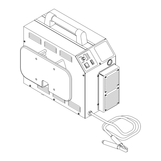
- Page 1 ® PAK MASTER 100XL Air Plasma Cutting Power Supply (CE) A-01355 Operating Manual Manual No. 0-2611 December 16, 1998...
- Page 3 While the information contained in this Operating Manual WARNING represents our best judgement, Thermal Dynamics Corporation assumes no liability for its use. ® Pak Master 100XL Air Plasma Cutting Power Supply (CE)
-
Page 4: Table Of Contents
TABLE OF CONTENTS SECTION 1: GENERAL INFORMATION ....................1 1.01 Notes, Cautions and Warnings ..............1 1.02 Important Safety Precautions ................ 1 1.03 Publications ....................2 1.04 Note, Attention et Avertissement ..............3 1.05 Precautions De Securite Importantes ............3 1.06 Documents De Reference ................ - Page 5 TABLE OF CONTENTS (continued) SECTION 6: PARTS LISTS ........................31 6.01 Introduction ....................31 6.02 Ordering Information ................... 31 6.03 Complete Power Supply Replacement ............32 6.04 Options and Accessories ................32 APPENDIX I: INPUT WIRING REQUIREMENTS ..............33 APPENDIX II: SEQUENCE OF OPERATION (BLOCK DIAGRAM) .......... 34 APPENDIX III: SYSTEM SCHEMATIC ..................
-
Page 7: General Information
• Use an air-supplied respirator if ventilation is not SECTION 1: adequate to remove all fumes and gases. GENERAL INFORMATION • The kinds of fumes and gases from the plasma arc depend on the kind of metal being used, coatings on the metal, and the different processes. -
Page 8: Publications
• Protect others in the work area from the arc rays. Use protective booths, screens or shields. FIRE AND EXPLOSION • Use the shade of lens as recommended in Subsec- tion 1.03, item 4. Fire and explosion can be caused by hot slag, sparks, or the plasma arc. -
Page 9: Note, Attention Et Avertissement
12. CSA Standard W117.2, CODE FOR SAFETY IN 1.05 Precautions De Securite WELDING AND CUTTING, obtainable from the Ca- Importantes nadian Standards Association, Standards Sales, 178 Rexdale Boulevard, Rexdale, Ontario, Canada M9W 13. NWSA booklet, WELDING SAFETY BIBLIOGRA- AVERTISSEMENT PHY obtainable from the National Welding Supply Association, 1900 Arch Street, Philadelphia, PA 19103 L’OPÉRATION ET LA MAINTENANCE DU 14. - Page 10 • Utilisez un équipement spécial tel que des tables de • Prévoyez une veille d’incendie lors de tout travail coupe à débit d’eau ou à courant descendant pour dans une zone présentant des dangers d’incendie. capter la fumée et les gaz. •...
-
Page 11: Documents De Reference
• Pour des renseignements sur la manière de tester le 9. Norme 70 de la NFPA, CODE ELECTRIQUE NA- bruit, consultez l’article 1, page 5. TIONAL, disponible auprès de la National Fire Pro- tection Association, Batterymarch Park, Quincy, MA 1.06 Documents De Reference 02269 10. -
Page 12: Declaration Of Conformity
Rigorous testing is incorporated into the manufacturing process to ensure the manufactured product meets or exceeds all design specifications. Thermal Dynamics has been manufacturing products for more than 30 years, and will continue to achieve excellence in our area of manufacture. -
Page 13: Statement Of Warranty
90 Days None Warranty repairs or replacement claims under this limited warranty must be submitted by an authorized Thermal Dynamics® repair facility within thirty (30) days of the repair. No transportation costs of any kind will be paid under this warranty. - Page 14 GENERAL INFORMATION...
-
Page 15: Introduction
NOTE 100XL Air Plasma Cutting Power Supply (CE). Service Refer to Section 2.04 for list of power supply op- of this equipment is restricted to Thermal Dynamics tions and accessories. trained personnel; unqualified personnel are strictly cau- tioned against attempting repairs or adjustments not cov- 2.03 Specifications/Design Features... -
Page 16: Power Supply Options And Accessories
9. Weight D. Interface Cable 79 lbs (35.8 kg) NOTE This accessory can be used only with the 10. Overall Dimensions PCM-100XL Torches. 18.9" (480 mm) High x 13" (330 mm) Wide x 25.5" (648 mm) Long The interface cable is available in two lengths, 25 ft (7.6 m) and 50 ft (15.2 m). -
Page 17: Installation Procedures
Provide sufficient clearance in front of the unit to allow SECTION 3: access to the front panel controls (minimum 6 inches or 0.15 m). INSTALLATION PROCEDURES CAUTION Operation without proper air flow will inhibit 3.01 Introduction proper cooling and reduce duty cycle. NOTE 3.03 Unpacking Depending on how the system was ordered, some... -
Page 18: Lifting Options
A. Input Voltage Selection 3.04 Lifting Options The Power Supply is factory-wired for 380/415V three- phase input. For any other input voltage, the Power Sup- WARNINGS ply must be changed using the procedure in Sections 3.06. B. Electrical Connections Do not touch live electrical parts. The power source must conform to local and national Disconnect input power conductors from de-en- electric codes. -
Page 19: Input Voltage Selection
3.06 Input Voltage Selection Voltage Selection A-01347 The Power Supply has three voltage settings; 208/230/ Block 240VAC, 380/415VAC, or 460VAC. Power Supplies are factory-wired for 380/415VAC three-phase input. In- put voltage selection is accomplished by switching an 460V internal buss bar and connector inside the Power Sup- 220V 220V 380-415V/460V... -
Page 20: Gas Connections
CAUTION CAUTION The primary power source, power cable, and plug The air supply must be free of oil, moisture, and all must conform to local electric code and the rec- other contaminants. Excessive oil and moisture ommended circuit protection and wiring require- may cause double-arcing, rapid tip wear, or even ments (refer to Appendix I). -
Page 21: Connecting Torch Leads
5. Refer to the following when using high pressure gas Regulator/Filter Assembly cylinders as the gas supply: CAUTION 1/4 NPT to #4 (6 mm) Hose Fitting Pressure should be set at 100 psi (6.9 BAR or 690 kPa) at the high pressure gas cylinder regulator. a. -
Page 22: Work Cable And Ground Connections
4. Feed the end of the torch leads through the hole in the front panel in the following order: Access Panel • Control Cable • Gas lead • Pilot Lead 5. Place the strain relief into the hole and secure with the nut removed in Step 3 above. - Page 23 B. Creating an Earth Ground 1. Install a ground wire (not included) between the sys- tem and a solid earth ground (also called star ground). To create a solid earth ground, drive a 1/2 in (12 mm) diameter copper rod approximately 6 - 8 ft (1.8 - 2.4 m) into the earth so that the rod contacts moist soil over most of its length.
- Page 24 INSTALLATION PROCEDURES Manual 0-2611...
-
Page 25: Operation
2. Access Panel SECTION 4: A panel to gain access to the bulkhead area contain- OPERATION ing the torch connections. 3. Torch Leads Input 4.01 Introduction Hole in the front panel to feed the torch leads through to the internal bulkhead connections. This Section provides a description of the Power Supply operating controls and procedures. - Page 26 4. AC Power Indicator 3. Gas/Power Lead Connection Green LED indicator will blink ON then OFF for ap- Connects the torch gas/negative lead to the unit. proximately eight seconds and then stay ON after D. Rear Panel the ON/OFF power switch is set to ON. Indicates operating power is present in the unit..
-
Page 27: Sequence Of Operation
4. Place RUN/SET switch to SET mode. a. Gas solenoid opens and gas flows to set pres- sure. b. GAS indicator turns ON. NOTE GAS indicator will not come ON if the gas pres- sure is set below 45 psi (3.1 BAR or 310 kPa) at the Regulator/Filter Assembly. -
Page 28: Preparations For Operating
12. Gas will flow for 15 seconds (post-flow). a. Gas solenoid closes Make a solid work cable connection to the work- b. Gas flow stops. piece or cutting table c. GAS indicator turns OFF. 13. Place the ON/OFF power switch on the front panel of the unit to OFF a. - Page 29 The following cut quality characteristics are illustrated T y p e o f M a t e r ia l in Figure 4-7 below: C a r b o n S t a in le s s G a s A lu m in u m S t e e l S t e e l...
- Page 30 OPERATION Manual 0-2611...
-
Page 31: Customer/Operator Service
Dynamics Trained personnel. comes into contact with the workpiece while the For major troubleshooting and parts replacement pro- torch is activated. cedures refer to PAK Master 100XL Power Supply (EMC) Service Manual 0-2612. 5.02 General Maintenance CAUTION Sparks from the cutting process can cause dam-... -
Page 32: Troubleshooting Guide
Cutting current too low For major troubleshooting and parts replacement pro- 2. Main Arc Extinguishes cedures refer to PAK Master 100XL Power Supply (EMC) Service Manual 0-2612. a. Cutting speed too slow b. Torch standoff too high from workpiece c. - Page 33 C. How to use this Guide 3. Unit is overheated a. Allow unit to cool down for about 5 minutes. The following information is a guide to help the Cus- Make sure the unit has not been operated be- tomer/Operator determine the most likely causes for yond duty cycle limit.
-
Page 34: Power Supply Parts Replacement
E. Low cutting output with no control 3. Excessive oil or moisture in torch 1. Incorrect setting of CURRENT control a. Hold torch 1/8 inch (3 mm) from clean surface while purging and observe oil or moisture a. Check and adjusted to proper setting. buildup (do not activate torch) 2. - Page 35 b. Reinstall all the screws to secure the left side panel. B. Fuse Replacement 1. Remove the left side panel per paragraph "A" above. 2. Locate the internal fuse above and behind the EMC Filter on the left side of the unit. 3.
- Page 36 SERVICE Manual 0-2611...
-
Page 37: Parts Lists
Parts listed without item numbers are not shown, but may be ordered by the catalog number shown. B. Returns If a Thermal Dynamics product must be returned for service, contact your Thermal Arc distributor. Materials returned to Thermal Dynamics without proper authori- zation will not be accepted. -
Page 38: Complete Power Supply Replacement
6.03 Complete Power Supply Replacement Power supply includes: CE Input Power Cable, Work cable, pressure regulator/air filter, air hose and fittings, and operating manual. Description Catalog # PAK Master 100XL Power Supply (CE) 3-0850 6.04 Options and Accessories Description Catalog #... -
Page 39: Appendix I: Input Wiring Requirements
APPENDIX I: INPUT WIRING REQUIREMENTS In p u t P o w er In p u t C u r r en t S u g g ested S iz es (S ee N o tes) V o ltag e F r eq . -
Page 40: Appendix Ii: Sequence Of Operation (Block Diagram)
APPENDIX II: SEQUENCE OF OPERATION (BLOCK DIAGRAM) ACTION ACTION ACTION ACTION ON/OFF switch Close external RUN/SET switch RUN/SET switch to ON. disconnect switch. to RUN. to SET. RESULT RESULT RESULT RESULT AC indicator blinks for 8 Power to system. Gas flow stops. Gas solenoid open, seconds then steady on. - Page 41 Manual 0-2611 APPENDIX...
-
Page 42: Appendix Iii: System Schematic
APPENDIX III: SYSTEM SCHEMATIC A-01564 APPENDIX Manual 0-2611... - Page 43 A-01564 Manual 0-2611 APPENDIX...
Need help?
Do you have a question about the PAK MASTER 100XL and is the answer not in the manual?
Questions and answers