
Related Manuals for Thermal Dynamics PAK Master 150XL


Summary of Contents for Thermal Dynamics PAK Master 150XL
- Page 1 Automated Plasma Cutting Power Supply ® PAK Master 150XL™ A-02861 Service Manual November 18, 2005 Manual No. 0-2825...
- Page 3 Manufacturer assumes no liability for its use. Automated Plasma Cutting Power Supply Pak Master ® 150XL Service Manual Number 0-2825 Published by: Thermal Dynamics Corporation 82 Benning Street West Lebanon, New Hampshire, USA 03784 (603) 298-5711 www.thermal-dynamics.com ©Copyright 2000 by Thermal Dynamics Corporation All rights reserved.
-
Page 4: Table Of Contents
TABLE OF CONTENTS SECTION 1: GENERAL INFORMATION ....................1-1 1.01 Notes, Cautions and Warnings ..............1-1 1.02 Important Safety Precautions ................ 1-1 1.03 Publications ....................1-2 1.04 Note, Attention et Avertissement ..............1-3 1.05 Precautions De Securite Importantes ............1-3 1.06 Documents De Reference ................ - Page 5 TABLE OF CONTENTS (Continued) SECTION 6: PARTS LISTS ........................6-1 6.01 Introduction ....................6-1 6.02 Ordering Information ..................6-1 6.03 Major External Replacement Parts ............... 6-2 6.04 Access Panel Replacement Parts ..............6-3 6.05 Left Side Center Chassis Replacement Parts ..........6-4 6.06 Right Side Center Chassis Replacement Parts ..........
- Page 6 TABLE OF CONTENTS (Continued) APPENDIX 18: FILTER/VOLTAGE DIVIDER PC BOARD LAYOUT .......... A-22 APPENDIX 19: SYSTEM SCHEMATIC for Units to Rev AH ............. A-24 APPENDIX 20: SYSTEM SCHEMATIC for Units Rev AJ and Later ........... A-26...
-
Page 7: General Information
SECTION 1: GASES AND FUMES GENERAL INFORMATION Gases and fumes produced during the plasma cutting process can be dangerous and hazardous to your health. 1.01 Notes, Cautions and Warnings • Keep all fumes and gases from the breathing area. Throughout this manual, notes, cautions, and warnings Keep your head out of the welding fume plume. -
Page 8: Publications
• Wear dry gloves and clothing. Insulate yourself from the work piece or other parts of the welding PLASMA ARC RAYS circuit. • Repair or replace all worn or damaged parts. Plasma Arc Rays can injure your eyes and burn your skin. •... -
Page 9: Note, Attention Et Avertissement
6. ANSI Standard Z49.2, FIRE PREVENTION IN THE USE OF NOTE CUTTING AND WELDING PROCESSES, obtainable from Toute opération, procédure ou renseignement American National Standards Institute, 1430 Broadway, New général sur lequel il importe d’insister davantage York, NY 10018 ou qui contribue à l’efficacité de fonctionnement 7. - Page 10 FUMÉE et GAZ CHOC ELECTRIQUE La fumée et les gaz produits par le procédé de jet de plasma Les chocs électriques peuvent blesser ou même tuer. Le procédé peuvent présenter des risques et des dangers de santé. au jet de plasma requiert et produit de l’énergie électrique haute tension.
-
Page 11: Documents De Reference
1.06 Documents De Reference RAYONS D’ARC DE PLASMA Consultez les normes suivantes ou les révisions les plus récentes ayant été faites à celles-ci pour de plus amples Les rayons provenant de l’arc de plasma peuvent blesser vos renseignements : yeux et brûler votre peau. Le procédé à l’arc de plasma produit 1. - Page 12 10. Norme 51B de la NFPA, LES PROCÉDÉS DE COUPE ET DE SOUDAGE, disponible auprès de la National Fire Pro- tection Association, Batterymarch Park, Quincy, MA 02269 11. Brochure GCA P-1, LA MANIPULATION SANS RISQUE DES GAZ COMPRIMÉS EN CYLINDRES, disponible auprès de l’Association des Gaz Comprimés (Compressed Gas Association), 1235 Jefferson Davis Highway, Suite 501, Arlington, VA 22202...
-
Page 13: Declaration Of Conformity
Rigorous testing is incorporated into the manufacturing process to ensure the manufactured product meets or exceeds all design specifications. Thermal Dynamics has been manufacturing products for more than 30 years, and will continue to achieve excellence in our area of manufacture. -
Page 14: Statement Of Warranty
None Warranty repairs or replacement claims under this limited warranty must be submitted by an authorized Thermal Dynamics® repair facility within thirty (30) days of the repair. No transportation costs of any kind will be paid under this warranty. Transportation charges to send products to an authorized warranty repair facility shall be the responsibility of the customer. -
Page 15: Introduction
C. Customer/Operator Responsibilities It is the customer/operator's responsibility to maintain the equipment and peripheral accessories provided by Thermal Dynamics in good operating order in accordance with the procedures outlined in the Operating Manual, and to protect the equipment from accidental or mali- cious damage. - Page 16 INTRODUCTION Manual 0-2825...
-
Page 17: Description
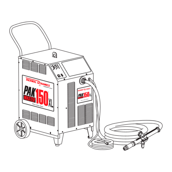
Power Supply is designed to cut most metals up to 1-1/2 inches (38 mm) using air, nitrogen, or argon/hydrogen as the plasma gas. This system is also capable of satisfy- Figure 3-1 Automated Pak Master 150XL System ing many mechanized gouging applications. The Automated Power Supply provides 120 amp maxi-... -
Page 18: Specifications/Design Features
7. Cut Capacity on Carbon Steel 3.03 Specifications/Design Features • Genuine Cut Capacity: 1-1/2 inch (38 mm) • Severance Cut: 1- 3/4 inch (44 mm) A. Power Supply Specifications • Pierce Rating: 5/8 inch (15.9 mm) The following specifications apply to the Power Supply 8. -
Page 19: Power Supply Options And Accessories
B. Gas Regulator/Filter Assembly 3.04 Power Supply Options and Specifications Accessories The following specifications apply to the Gas Regulator/ The following accessories are available for the Power Filter Assembly only: Supply. Refer to Section 6, Parts Lists, for part numbers 1. -
Page 20: Theory Of Operation
F. Interlocks 2.05 Theory Of Operation The system has several built-in interlocks to provide safe A. Plasma Arc Cutting and Gouging and efficient operation. When an interlock shuts down the system, the fault condition must be remedied and the Plasma is a gas which is heated to an extremely high tem- system recycled using the applicable control device. -
Page 21: Service
4.01 Introduction may be used. This Section provides service diagnostics for the Auto- mated Pak Master 150XL Power Supply, allowing the Tech- WARNING nician to isolate any faulty subassemblies. Refer to Sec- tion 5, Repairs & Replacement Procedures, for parts replacement instructions. - Page 22 To accurately measure the coolant conductivity it is recommended to use a Conductivity Sensor simi- Reconnect the hose to the Coolant Filter Assembly. lar to Thermal Dynamics Model TDS-73 (Catalog Remove Coolant Reservoir lid and install new cool- # 7-2844).
-
Page 23: System Theory
The resulting current is sensed by the Current Sense 4.03 System Theory PC Board, resulting in the demand level changing from pilot current to whatever the main current control is The system is designed for mechanized (automated) cut- set at. During the "transfer" the CSR Indicator (D65) ting operations using the torch control bulkhead and rear comes ON and the transfer enable signal goes low al- panel as the interface. - Page 24 C. Gate Drive PC Board Functions E. Current Sense PC Board Functions NOTE NOTE Refer to Appendix 5 for Gate Drive PC Board lay- Refer to Appendix 11 for Current Sense PC Board out. layout. This board controls the amount of time the FETs are turned This board senses current in the work lead (approxi- on.
-
Page 25: Common Operating Problems
E. Dross 4.04 Common Operating Problems When dross is present on carbon steel, it is commonly referred to as either “high speed, slow speed, or top WARNINGS dross”. Dross present on top of the plate is normally caused by too great a torch to plate distance. "Top dross"... -
Page 26: Troubleshooting Guide - General Information
Section 4.10 - Test Procedures Incorrect torch parts for the operation C. How to Use the Troubleshooting Guide g. Non-Genuine Thermal Dynamics parts used The following information is a guide to help the Service 4.05 Troubleshooting Guide - Technician determine the most likely causes for various symptoms. -
Page 27: Circuit Fault Isolation
Set the Power Supply RUN/SET switch to the RUN posi- 4.06 Circuit Fault Isolation tion and note the following: This section is used before troubleshooting to help isolate • Gas Indicator goes OFF the defective circuit, identify symptoms, and test the unit for proper operation. -
Page 28: Main Input And Internal Power Problems
D. Main Arc Test C. AC indicator on front panel of power supply is OFF 1. Front Panel ON/OFF switch in OFF position Activate START signal from CNC or press the torch switch on the Remote Pendant to establish a pilot arc. a. - Page 29 D. AC indicator ON, TEMP indicator ON, RUN/SET F. AC indicator ON; GAS indicator OFF; Gas flows; Switch is in RUN position, System will not pilot DC indicator OFF 1. Air flow through unit is restricted 1. Gas pressure too low a.
-
Page 30: Pilot Arc Problems
6. Faulty Flow Switch (FS1) or Logic PC Board 4.08 Pilot Arc Problems a. Check the coolant flow switch and Logic Board NOTE as follows: Refer to the Appendix Pages for PC Board Layouts. The flow switch (FS1) for the coolant is cali- brated for 0.25 gpm. - Page 31 4. Faulty Logic PC Board or Gate PC Board (see note above) B. AC indicator ON; Gas flows; GAS indicator ON; DC indicator blinks; Small arc may be visible in torch a. Close the torch switch. The LED D20 on the top Gate PC Board should turn off.
-
Page 32: Main Cutting Arc Problems
7. Faulty Pilot Output PC Board 4. Faulty Current Sensor PC Board a. D5 on the Pilot PC Board should turn on two Check the following: seconds after the START signal is activated. a. While trying to initiate main cutting arc, mea- sure the voltage at J99-6 to J99-7 (or TP 10 to •... -
Page 33: Test Procedures
5. Remove the nut securing the ground wire to the side 4.10 Test Procedures panel and remove the ground wire. The test procedures in this subsection are referenced in 6. Remove Side Panel from unit and set aside. the troubleshooting section. A. - Page 34 D. Input PC Board /Input Bridge Rectifier Test Locate the Input PC Board and check for shorted input Art # A-00307 diode. NOTE 0.75 Refer to the Appendix Pages for PC Board Layouts. Remove AC power and with an ohmmeter set on the diode Forward Bias range make the following checks: Diode Conducting...
- Page 35 E. Main Contactor (MC1) Test H. Temperature Circuit Test Reconnect power and observe proper start-up procedure. The Power Supply has seven temperature sensing Indicator D47 on the Logic PC Board should be ON. If switches. indicator D47 is OFF there is no voltage to the Power Sup- •...
- Page 36 Place the front panel ON/OFF switch to the OFF Gas Solenoid Circuit Test position. NOTE 6. Disconnect ribbon cable from the next FET/Heat- Refer to the Appendix Pages for PC Board layouts, sink Assembly at J6. as required. Place the front panel ON/OFF switch to ON. Make the following voltage checks per the circuit dia- Check status of the TEMP Indicator.
- Page 37 K. FET/Heatsink Circuit Tests If the front panel DC Indicator turns ON then OFF im- mediately, the following test should be performed: NOTE a. Disconnect J11 from the CD PC Board to disable Refer to the Appendix Pages for PC Board Lay- the CD signal.
- Page 38 3. MOSFET Resistance Checks 4. FET Reset Diode Check The Power Supply contains four identical FET/Heat- Use an ohmmeter set to the diode function and check sink Assemblies. On each assembly there are two the reset diode as follows: MOSFET devices that must be checked. Use an ohm- Place the meter (+) lead on E14 and the meter (-) meter to check for the proper resistance of the lead on E12 of the FET/Heatsink Assembly Capaci-...
- Page 39 Place the meter (+) lead on E18 and the meter (-) 6. FET Output Clamp Diodes Check lead on E16 of the FET/Heatsink Assembly to check NOTE the output rectifier reverse bias. The meter should indicate 'OL' using the diode function or 100K ohms Refer to the Appendix Pages for PC Board Lay- using the ohms function.
- Page 40 SERVICE 4-20 Manual 0-2825...
-
Page 41: Replacement Procedures
Auto- 4. Connect the equipment primary cable ground to mated Pak Master 150XL Power Supply. the same electrical ground as the wrist strap. Under no circumstances are field repairs to be attempted 5. -
Page 42: Major External Parts Replacement
Each Subsection is referenced to Section 6 for parts lists 7. Install the replacement Side Panel by reversing the and overall detailed drawing. above procedure doing the following: a. Reconnect the ground wire to the Side Panel, if disconnected. WARNING b. -
Page 43: Access Panel Parts Replacement
D. Torch & Leads Assembly Replacement B. ON/OFF Switch (SW1) Replacement 1. Open the Access Panel per Section 5.05-E. 1. Unlatch the Access Panel to gain access to the rear of the ON/OFF Switch. 2. Disconnect all hoses and the cable from the bulk- head. -
Page 44: Left Side Center Chassis Parts Replacement
D. Pot/LED PC Board Assembly Replacement 5.06 Left Side Center Chassis Parts Replacement 1. Turn the CURRENT adjustment fully counter clockwise and note the location of the pointer on NOTE the knob. Refer to Section 6.05 for parts list and overall de- 2. - Page 45 C. Input PC Board Assembly Replacement D. Input Bridge Rectifier Replacement 1. Remove the Left Side Panel per Section 5.04-A. 1. Remove the Left Side Panel per Section 5.04-A. 2. Disconnect all cable lug connections to Input 2. Remove the Input PC Board per Section 5.06-C. Board, removing star washers and nuts where 3.
- Page 46 G. Logic PC Board Replacement FET/Heatsink Assembly Replacement 1. Remove the Left Side Panel per section 5.04-A. CAUTION 2. Carefully remove all cable connections from the Logic PC Board noting the location of each. The FET / Heatsink Assemblies are matched and balanced during production and must be replaced 3.
- Page 47 Install the replacement Main Contactor Assembly by reversing the above steps, connecting wires as follows: a. Connect ground wire as shown. Replace As Pair Input 2-Brass Side Board Nuts Panel Ground Replace As Ground Pair 3-Star Washers A-02584 A-02291 Main Install the replacement FET/Heatsink Assembly by Harness Ground...
-
Page 48: Right Side Center Chassis Parts Replacement
C. Pilot Resistor (R1 & R2) Replacement 5.07 Right Side Center Chassis Parts Replacement NOTE This unit has two Pilot Resistors. The replacement NOTE instructions are the same for both. Refer to Section 6.06 for parts list and overall de- 1. - Page 49 F. Coolant Filter Replacement c. Remove the Coolant Reservoir Cap then remove the Deionizer Basket and Deionizer Bag from Remove Right Side Panel per Section 5.04-A. the Coolant Reservoir filler hole. Remove the two coolant hose connections to the 3. Disconnect the Coolant Supply Hose output con- Filter Assembly.
- Page 50 H. In-Line Coolant Filter Assembly Flow Switch (FS1) Assembly Replacement Replacement Remove the Right Side Panel per Section 5.04-A. 1. Remove the Right Side Panel per Section 5.04-A. CAUTION CAUTION Handle and dispose of the used coolant per recom- mended procedures. Handle and dispose of the used coolant per recom- mended procedures.
- Page 51 J. Output Inductor (L1 & L2) Assembly 10. Locate the two nuts on the base which secure the reservoir panel to the base, then remove nuts. Replacement NOTE NOTES It may be necessary to disconnect some wiring in There are two Output Inductors in this unit. Re- order to have enough room to work.
- Page 52 K. Main Transformer (T1 & T2) Assembly Slide reservoir panel up and out of the 'T' slots on the center chassis and move panel to provide ac- Replacement cess to main transformers. NOTES 10. Carefully remove all wire connections to the FET There are two Main Transformers in this unit.
- Page 53 L. Pilot Panel Fan (M1 - M4) Replacement M. Current Sense PC Board Assembly Replacement NOTE 1. Remove the Work Cable per Section 5.04-C. There are four Fans mounted to the Pilot Fan Panel. Replacement instructions are the same for all Fans. Disconnect the ribbon cable from the Current Sen- sor at J17 on the Logic PC Board.
-
Page 54: Base Parts Replacement
B. Support Leg(s) Assembly Replacement 5.08 Base Parts Replacement NOTE A. Wheel/Axle Assembly Replacement Both support leg assemblies are removed and re- • Wheel Replacement placed in a similar manner. NOTE Raise the unit off the floor far enough for the weight of the unit to be removed from the support legs. - Page 55 D. Motor (M5) / Fan / Pump Replacement E. Fan Assembly Only Replacement NOTE Remove Motor/Fan/Pump Assembly from unit per procedure in 5.08-D. The simplest way to replace the Motor is to remove the Motor, Fan and Pump together, then replace Loosen the fan locking screw securing the Fan to the Motor.
-
Page 56: Rear Panel Parts Replacement
Install the replacement Pump Assembly by revers- 5.09 Rear Panel Parts Replacement ing the above steps, noting the following: NOTE a. Proper orientation of the Pump Assembly to the Motor Assembly. Refer to Section 6.08 for parts list and overall de- tail drawing. - Page 57 f. Note solenoid/pressure switch orientation, D. Solenoid Valve (SOL1 & SOL2) then remove the solenoid/pressure switch as- Replacement sembly from the 2 inch brass nipple, and set NOTE aside. There are two Solenoid Valve Assemblies in this g. Remove the four screws securing each regula- unit;...
- Page 58 E. Air Line Regulator Bracket(s) Replacement Remove the Regulator from the 2 inch brass nipple connected to the Solenoid Assembly. NOTE 6. Remove the elbow fitting from the old assembly. There are two Air Line Regulator Brackets in this 7. Install the replacement Air Line Regulator Assem- unit and both are replaced using this same proce- bly by reversing the above procedure, keeping in dure.
-
Page 59: Parts Lists
SECTION 6: PARTS LISTS 6.01 Introduction A. Parts List Breakdown The parts lists provide a breakdown of all replaceable components. Parts are organized as follows: Section 6.03 Major External Replacement Parts Section 6.04 Access Panel Replacement Parts Section 6.05 Left Side Center Chassis Replacement Parts Section 6.06 Right Side Center Chassis Replacement Parts... -
Page 60: Major External Replacement Parts
6.03 Major External Replacement Parts Item # Description Catalog # RIGHT PANEL W/LABELS 9-7819 LEFT SIDE PANEL W/LABELS 9-7818 FRONT PANEL W/LABELS 9-7816 REAR PANEL - Refer to Section 6.08 for Parts List TOP PANEL 9-7797 ACCESS PANEL - Refer to Section 6.04 for Parts List CABLE, WORK, 22' #4 AWG W/RING TERMINAL 9-7792 BOOT, RUBBER... -
Page 61: Access Panel Replacement Parts
6.04 Access Panel Replacement Parts Item # Description Ref # Catalog # ASS’Y, POT/LED PCB 9-8004 SWITCH, ROCKER, SPST 9-1042 ON/OFF ROCKER SWITCH, DPST 8-3258 KNOB, CURRENT CONTROL W/FOAM SEAL 9-8007 ASSEMBLY, ACCESS PANEL w/Overlay 9-7821 “DZUS” STUD 9-4346 “DZUS” RETAINING RING 9-4347 POT PROTECTION KIT includes: 7-7575... -
Page 62: Left Side Center Chassis Replacement Parts
6.05 Left Side Center Chassis Replacement Parts Item # Description Ref # Catalog # FUSE BLOCK, 9-5562 FUSE, 5 AMP, 600V,DELAY, FNQ-R-5 10-2274 INPUT PCB ASSEMBLY 9-7813 ASSEMBLY BRIDGE RECTIFIER, 110A 3PH 9-7824 BRIDGE RECTIFIER, 110A 3PH 9-7800 THERMAL PAD, QIII, INPUT MODULE THERMOSTAT, CLOSES @ 80c RISING 9-7895 CONTACTOR, 4 POLE, 40 FLA, 120 VAC (In-Rush Contactor) - Page 63 A-02274 Manual 0-2825 PARTS LISTS...
-
Page 64: Right Side Center Chassis Replacement Parts
6.06 Right Side Center Chassis Replacement Parts Item # Description Ref # Catalog # PILOT/OUTPUT PCB ASSEMBLY 9-7809 RELAY, DPST, 25A MAX, 120 AC (Coolant Motor Relay) 8-3390 RESISTOR R1,R2 9-5843 INDUCTOR, PILOT 9-7801 CD PCB ASSEMBLY 9-7814 COOLANT FILTER 8-4276 COOLANT RESERVOIR 9-5948... - Page 65 A-02275 NOTE: Parts may differ slightly from illustration Manual 0-2825 PARTS LISTS...
-
Page 66: Base Replacement Parts
6.07 Base Replacement Parts Item # Description Ref # Catalog # WHEEL 8-5579 AXLE 9-7891 SUPPORT LEG 9-7892 TRANSFORMER,AUXILIARY (220,395,460) 9-7802 Fuse, 5A, 250V Delay MDL-5 (in Torch Spare Parts Kit) 9-8109 FAN, MEDIUM PRESSURE, 8" DIA. 9-7893 MOTOR, 1/3 HP, 1425/1725 RPM, 115/230 V, 50/60 HZ 9-5932A PUMP, ROTARY - VANE TYPE 9-6164... - Page 67 23x4274 A-02929 Manual 0-2825 PARTS LISTS...
-
Page 68: Rear Panel Replacement Parts
6.08 Rear Panel Replacement Parts Item # Description Ref # Catalog # HANDLE (WITH SCREWS) 9-7822 PRESSURE SWITCH-35 PSI, 9-1044 VALVE, SOLENOID 1/8 NPT, SOL1, SOL2 8-3370 AIR REGULATOR/FILTER ASSEMBLY AIR LINE REGULATOR 9-7514 PRESSURE GAUGE 9-1045 PANEL MOUNTING NUT 9-5804 BRACKET, REGULATOR MOUNTING 9-7589... - Page 69 A-02930 Manual 0-2825 6-11 PARTS LISTS...
-
Page 70: Options And Accessories
6.09 Options and Accessories Description Catalog # 575V Transformer Module 9-7700 Primary Input Power Cable, 10 ft. (3.05 m) 230VAC, 2AWG, 4 COND, 600V 9-7697 460VAC, 6AWG, 4 COND, 600V 9-7696 "Y" Hose Assembly Kit 9-7827 Locking Caster Kit (2 Casters) 9-7868 Remote Pendant Control, 20 ft (6.1 m) 7-3460... -
Page 71: Appendix 1: Input Wiring Requirements
APPENDIX 1: INPUT WIRING REQUIREMENTS Input Power Input Current Suggested Sizes (See Notes) Voltage Freq. 3-Ph 3-Ph Fuse (Amps) Wire (AWG) Wire (Canada) (Volts) (Hz) (kVA) (Amps) 3-Ph 3-Ph 3-Ph 50/60 28.1 50/60 28.6 50/60 29.5 50/60 29.9 50/60 29.0 50/60 29.5 50/60... -
Page 72: Appendix 2: Sequence Of Operation (Block Diagram
APPENDIX 2: SEQUENCE OF OPERATION (BLOCK DIAGRAM) ACTION ACTION ACTION ACTION ON/OFF switch Close external RUN/SET switch RUN/SET switch to ON. disconnect switch. to RUN. to SET. RESULT RESULT RESULT RESULT AC indicator blinks for 8 Power to system. Gas flow stops. Gas solenoid open, seconds then steady on. -
Page 73: Appendix 3: Pot/Led Pc Board Layout
APPENDIX 3: POT/LED PC BOARD LAYOUT A-01206 Pot/LED PC Board Signals J14-1 +10 vdc from Logic PC Board (J3-7) - Potentiometer High J14-2 Current Control to Logic PC Board (J3-8) - Potentiometer Wiper J14-3 Return for Current Control from Logic PC Board (J3-9) - Potentiometer Low J14-4 +12 vdc from Logic PC Board (J3-10) J14-5... -
Page 74: Appendix 4: Logic Pc Board Layout
APPENDIX 4: LOGIC PC BOARD LAYOUT TP1 (Ground) Logic PC Board A-02310 Logic PC Board Signals J2-11 Over Temp Sw. (Input Bridge, Pilot Bd, Radiator) 12V J2-12 Over Temp Sw. (Input Bridge, Pilot Bd, Radiator) Return J1-1 36 VAC from Auxiliary Transformer J2-13 Not Used J1-2... - Page 75 J3-10 +12 vdc J95-1 Not Used J3-11 Active Low Signal for AC Indicator on Front Panel (J14-5) J95-2 Not Used J3-12 Active Low Signal for GAS Indicator on Front Panel (J14-6) J3-13 Active Low Signal for TEMP Indicator on Front Panel (J14-7) J96-1 115VAC to Fans M3 &...
-
Page 76: Appendix 5: Gate Drive Pc Board Layout
APPENDIX 5: GATE DRIVE PC BOARD LAYOUT TP16 TP15 TP11 TP12 TP13 TP10 TP14 Gate Drive PC Board Signals J7-1 +12 vdc to FET PC Boards (J6-1) J7-2 Return for +12 vdc to FET PC Boards (J6-2) J7-3 PWM Output (A) to FET PC Boards (J6-3) Gate Drive PC Board A-02323 J7-4... - Page 77 J9-1 36 VAC (b) from Logic PC Board (J4-1) J9-2 36 VAC (a) from Logic PC Board (J4-2) J9-3 36 VAC (a) from Logic PC Board (J4-3) J9-4 36 VAC (b) from Logic PC Board (J4-4) J9-5 36 VAC CT Return from Logic PC Board (J4-5) J9-6 Return for Transfer Mod Enable J9-7...
-
Page 78: Appendix 6: Pilot/Output Pc Board Layout And Wiring Connection Diagram
APPENDIX 6: PILOT/OUTPUT PC BOARD LAYOUT AND WIRING CONNECTION DIAGRAM Pilot/Output PC Board A-02311 Pilot Output PC Board Signals J12-1 START Signal from J23-8 Filter/Divider PC Board J12-2 Shield to J26-1 J12-3 START Signal from J23-9 Filter/Divider PC Board J12-4 Shield to J26-2 J12-5 Not Used... - Page 79 J13-1 Active Low START signal Ground J13-2 START Signal Return +15 vdc J13-3 OK-To-Move (Isolated Contacts from Logic PC Board) Pilot Switch to Gate Drive PC Board J13-4 OK-To-Move (Isolated Contacts from Logic PC Board) Pilot Drive Signal J13-5 Ground Not Used J13-6 Not Used...
-
Page 80: Appendix 7: Cd Pc Board Layout
APPENDIX 7: CD PC BOARD LAYOUT J11-1 J11-3 J11-4 J11-5 A-01208 CD PC Board Signals J11-1 36 VAC (b) from Logic PC Board (J5-1) J11-2 36 VAC CT Return (J5-2) J11-3 36 VAC (a) from Logic PC Board (J5-3) J11-4 Active Low CD Enable Signal from Logic PC Board (J5-4) J11-5 Return for CD Enable Signal from Logic PC Board (J5-5) -
Page 81: Appendix 8: Input Pc Board Layout
APPENDIX 8: INPUT PC BOARD LAYOUT Component Side of PC Board Solder Side of PC Board CGND A-02313 Input PC Board AC Input (L1) AC Input (L2) AC Input (L3) Rectifier (-) Output Rectifier (-) Output Rectifier (+) Output Power ON Indicator Rectifier (+) Output to INR Rectifier (+) Output to INR Rectifier (-) Output to Capacitor PC Boards (A &... -
Page 82: Appendix 9: Fet Pc Board Layout
APPENDIX 9: FET PC BOARD LAYOUT Component Side Of PC Board XFMR SEC - OUTPUT MAIN XFMR PRI MAIN XFMR PRI MAIN XFMR SEC + OUTPUT FET PCB ASSY A-00479 Solder Side Of PC Board APPENDIX A-12 Manual 0-2825... - Page 83 FET PC Board Signals (Upper and Lower Assemblies) J6-1 +12 vdc from the Gate Drive Board upper J7-1 Lower J8-1 J6-2 +12 vdc RTN from the Gate Drive Board upper J7-2 Lower J8-2 J6-3 PWM Output from the Gate Drive Board upper J7-3 Lower J8-3 J6-4 PWM Output RTN J6-2 from the Gate Drive Board upper J7-4 Lower J8-4 J6-5...
-
Page 84: Appendix 10: Capacitor Pc Board Layout
APPENDIX 10: CAPACITOR PC BOARD LAYOUT E12A E12B E13A E13B A-01418 E12C E13C Capacitor PC Board Signals Positve Rail to FET Board E12A Positve Rail to FET Board E12B Positve Rail to FET Board E12C Positve Rail to FET Board Negative Rail to FET Board E13A Negative Rail to FET Board... -
Page 85: Appendix 11: Current Sensor Pc Board Layout
APPENDIX 11: CURRENT SENSOR PC BOARD LAYOUT A-01419 Current Sensor PC Board Signals J15-1 Active Low CSR Sense Signal J15-2 Ground J15-3 +12 vdc Manual 0-2825 A-15 APPENDIX... -
Page 86: Appendix 12: 36Vac Circuit Diagram
APPENDIX 12: 36VAC CIRCUIT DIAGRAM Pilot/Output CD PC Board PC Board 14 15 16 17 18 19 Logic PC Board Gate Drive Auxiliary 36 VAC PC Board Transformer Outputs 115 VAC Input Voltage Sense A-02325 J3 3 1 2 4 ON/OFF Switch Gate Drive... -
Page 87: Appendix 13: Recommended Routine Maintenance Schedule For Liquid Cooled Plasma Cutting Systems
APPENDIX 13: RECOMMENDED ROUTINE MAINTENANCE SCHEDULE FOR LIQUID COOLED PLASMA CUTTING SYSTEMS This schedule applies to all types of liquid cooled plasma cutting systems. Some systems will not have all the parts listed and those checks need not be performed. NOTE The actual frequency of maintenance may need to be adjusted according to the operating environment. -
Page 88: Appendix 14: Typical Mechanized System Grounding Diagram
APPENDIX 14: TYPICAL MECHANIZED SYSTEM GROUNDING DIAGRAM Connection for Systems Without Standoff Control CNC Control CNC Control Standoff Control Earth Ground Plasma Power Supply 3-Phase Input Work Cable Workpiece Earth Ground Earth Ground A-02883 NOTE Work Cable must connect direct to workpiece. DO NOT connect Work Cable to earth ground and then to workpiece. -
Page 89: Appendix 15: Power Supply Cnc Interface Diagram Without Standoff Control
APPENDIX 15: POWER SUPPLY CNC INTERFACE DIAGRAM WITHOUT STANDOFF CONTROL NOTE Cable connections from Cutting Machine Controller (CNC) to Plasma Power Supply without any Standoff Control Accessory. Cutting Machine CNC Cable Power Supply START/STOP Start Arc V Signal (SC11) Arc V (w/ 100K in Series) Start Motion OK-To-Move (OK-To-Move) -
Page 90: Appendix 16: Typical Mechanized System Cable Interconnection Diagram
APPENDIX 16: TYPICAL MECHANIZED SYSTEM CABLE INTERCONNECTION DIAGRAM NOTE Refer to Appendix XVII for com- plete data on the Cables and Hoses. External +48 vdc 120/220 VAC Power Supply CNC CONTROL SC-11 Standoff With Standoff Control Control CNC CONTROL Without Standoff Control Torch Torch Lifter Assembly... -
Page 91: Appendix 17: Quick Reference To Interconnecting Cables And Hoses
APPENDIX 17: QUICK REFERENCE TO INTERCONNECTING CABLES AND HOSES Identifier Description Catalog # Remote Standoff Control Cable 50 ft (15.2 m) 9-9021 75 ft (22.9 m) 9-9022 100 ft (30.5 m) 9-9023 Work Cable, 22 ft (6.7 m) 9-7792 Lifter Motor Cable 10 ft (3.0 m) 9-4535 15 ft (4.6 m) - Page 92 APPENDIX 18: FILTER/VOLTAGE DIVIDER PC BOARD LAYOUT Filter/Voltage Divider PC Board A-02872 (GND) APPENDIX A-22 Manual 0-2825...
- Page 93 Filter/Voltage Divider PC Board Signals Signals and Bias Power To and From Plasma Power Supply J23-1 Negative Arc voltage input form plasma power supply J23-2 Not Used J23-3 Not Used J23-4 Positive arc voltage (system common connection, work lead) J23-5 Printed Circuit Board (PCB) power supply common J23-6 Printed Circuit Board (PCB) power supply (24-36 VAC C.T.
- Page 94 APPENDIX 19: SYSTEM SCHEMATIC for Units to Rev AH A-02868 APPENDIX A-24 Manual 0-2825...
- Page 95 A-02868 Manual 0-2825 A-25 APPENDIX...
- Page 96 APPENDIX 20: SYSTEM SCHEMATIC for Units Rev AJ and Later Art # A-04332...
- Page 97 Art # A-04332...
Need help?
Do you have a question about the PAK Master 150XL and is the answer not in the manual?
Questions and answers