
Subscribe to Our Youtube Channel
Related Manuals for Thermal Dynamics PAK Master 150XL


Summary of Contents for Thermal Dynamics PAK Master 150XL
- Page 1 PLASMA CUTTING POWER SUPPLY ® ™ PAK Master 150XL Without Latch Circuit A-02072 Operating Manual December 21, 2004 Manual No. 0-2696...
- Page 3 Manufacturer assumes no liability for its use. Plasma Cutting Power Supply PAK Master150XL Without Latch Circuit Operating Manual Number 0-2696 Published by: Thermal Dynamics Corporation 82 Benning Street West Lebanon, New Hampshire, USA 03784 (603) 298-5711 www.thermal-dynamics.com Copyright 1998 by Thermal Dynamics Corporation All rights reserved.
-
Page 4: Table Of Contents
TABLE OF CONTENTS SECTION 1: GENERAL INFORMATION ....................1-1 1.01 Notes, Cautions and Warnings ..............1-1 1.02 Important Safety Precautions ................ 1-1 1.03 Publications ....................1-2 1.04 Note, Attention et Avertissement ..............1-3 1.05 Precautions De Securite Importantes ............1-3 1.06 Documents De Reference ................ - Page 5 TABLE OF CONTENTS (continued) SECTION 5: SERVICE .......................... 5-1 5.01 Introduction ....................5-1 5.02 General Maintenance ..................5-1 5.03 Common Operating Faults ................5-3 5.04 Common Operating Problems ............... 5-3 5.05 Troubleshooting Guide .................. 5-4 5.06 Power Supply Parts Replacement ..............5-7 SECTION 6: PARTS LISTS ........................
-
Page 7: General Information
SECTION 1: GASES AND FUMES GENERAL INFORMATION Gases and fumes produced during the plasma cutting process can be dangerous and hazardous to your health. 1.01 Notes, Cautions and Warnings • Keep all fumes and gases from the breathing area. Throughout this manual, notes, cautions, and warnings Keep your head out of the welding fume plume. -
Page 8: Publications
• Wear dry gloves and clothing. Insulate yourself from the work piece or other parts of the welding PLASMA ARC RAYS circuit. • Repair or replace all worn or damaged parts. Plasma Arc Rays can injure your eyes and burn your skin. •... -
Page 9: Note, Attention Et Avertissement
6. ANSI Standard Z49.2, FIRE PREVENTION IN THE USE ATTENTION OF CUTTING AND WELDING PROCESSES, obtain- able from American National Standards Institute, 1430 Broadway, New York, NY 10018 Toute procédure pouvant résulter l’endommagement du matériel en cas de non- 7. AWS Standard A6.0, WELDING AND CUTTING CON- respect de la procédure en question. - Page 10 • Eloignez toute fumée et gaz de votre zone de respira- • Ne touchez jamais une pièce “sous tension” ou “vive”; tion. Gardez votre tête hors de la plume de fumée portez des gants et des vêtements secs. Isolez-vous provenant du chalumeau. de la pièce de travail ou des autres parties du circuit de soudage.
-
Page 11: Documents De Reference
ultra-violets très forts. Ces rayons d’arc nuiront à vos 1.06 Documents De Reference yeux et brûleront votre peau si vous ne vous protégez pas correctement. Consultez les normes suivantes ou les révisions les plus récentes ayant été faites à celles-ci pour de plus amples •... - Page 12 9. Norme 70 de la NFPA, CODE ELECTRIQUE NA- TIONAL, disponible auprès de la National Fire Pro- tection Association, Batterymarch Park, Quincy, MA 02269 10. Norme 51B de la NFPA, LES PROCÉDÉS DE COUPE ET DE SOUDAGE, disponible auprès de la National Fire Protection Association, Batterymarch Park, Quincy, MA 02269 11.
-
Page 13: Declaration Of Conformity
Rigorous testing is incorporated into the manufacturing process to ensure the manufactured product meets or exceeds all design specifications. Thermal Dynamics has been manufacturing products for more than 30 years, and will continue to achieve excellence in our area of manufacture. -
Page 14: Statement Of Warranty
None Warranty repairs or replacement claims under this limited warranty must be submitted by an authorized Thermal Dynamics® repair facility within thirty (30) days of the repair. No transportation costs of any kind will be paid under this warranty. Transportation charges to send products to an authorized warranty repair facility shall be the responsibility of the customer. -
Page 15: Introduction
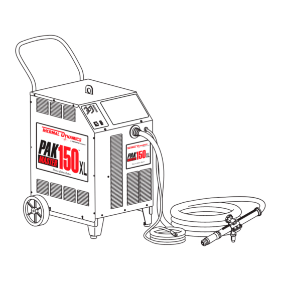
A-02072 ment will assure the dependable operation for which it was designed. Figure 2-1 Pak Master 150XL System 2.02 Power Supply General The Extra-Cool Coolant supplied with the Power Supply can Description be used in ambient temperatures down to 10°... -
Page 16: Specifications/Design Features
8. Pilot Circuitry 2.03 Specifications/Design Features Capacitive Discharge (CD), Pulsed DC 9. CNC Interface Signals A. Power Supply Specifications Start/Stop and OK-To-Move The following specifications apply to the Power Supply only: 10. Coolant Pressure 1. Front Panel Controls Internal Service Adjustable (Factory Only) •... -
Page 17: Power Supply Options And Accessories
B. Gas Regulator/Filter Assembly 2.04 Power Supply Options and Specifications Accessories The following specifications apply to the Gas Regulator/ NOTE Filter Assembly only: Refer to Section 6, Parts Lists, for part numbers 1. Gas Regulator Maximum Gauge Pressure and ordering information. Plasma: 160 psi (11.3 bar) The following are accessories that are available for the Secondary: 160 psi (11.3 bar) -
Page 18: Theory Of Operation
G. Remote Pendant Control wire for establishing an earth ground and shielded torch and control leads. The CNC control signals are filtered on an inter- NOTE nal PC Board. Accessory is for use with Unshielded PCM Torch F. Interlocks & Leads. The system has several built-in interlocks to provide safe Control used to manually start and stop cutting op- and efficient operation. -
Page 19: Installation
SECTION 3: CAUTION INSTALLATION Operation without proper air flow will inhibit proper cooling and reduce duty cycle. 3.01 Introduction 3.03 Unpacking NOTE NOTE Depending on how the system was ordered, some Equipment that was ordered as a system is pack- Power Supply options may already be installed. -
Page 20: Input Power Connections
3.05 Input Power Connections The Power Supply accepts input voltages in ranges from 208/ 230/460 VAC or 220/380-415 VAC, 50 or 60 Hz, three-phase power. NOTE: Art may differ NOTE from actual unit. Refer to Section 3.06, Input Voltage Selection. A. - Page 21 Power supplies are factory-wired for HIGH VOLTAGE, either 8. Tighten all the nuts. 460VAC or 380-415VAC, as ordered. Voltage can be changed NOTE from HIGH VOLTAGE to 208/230 VAC or 220 VAC (low voltage), as follows: If changing from low voltage to HIGH VOLTAGE all nuts must be tightened even if not used on the terminal block.
-
Page 22: Input Power Cable Connections
3. Connect input power conductor wires as follows: 3.07 Input Power Cable Connections a. Loosen L1, L2, and L3 set screws on the Main Con- tactor. b. Insert the three live conductor wires into the L1, WARNING L2, and L3 terminals on the contactor as follows: •... -
Page 23: Gas Connections
The following procedure is the recommended shop air connec- 3.08 Gas Connections tion method: The Power Supply provides the liquid cooling and gases 1. Locate the 1/4 NPT to #4 (6 mm) barbed hose fitting shipped to support operation of the Torch. inside the Torch Spare Parts Kit. - Page 24 B. Using Shop Air Only with Optional Two C. Using High Pressure Gas Cylinders Only Stage Filter Assembly NOTES NOTE Refer to the manufacturer’s specifications for in- stallation and maintenance procedures. Refer to For units where the Optional Two Stage Air Line sales literature for a listing of available high-pres- Filter has not been factory installed, install the Fil- sure regulators and accessories.
- Page 25 A-02948 Inert B Fittings Secondary Air Plasma Air Regulator Assembly Regulator Assemby Plasma Gas Supply Hose From Gas Secondary Gas Cylinder Supply Hose From Gas Cylinder A-02331 1/4 NPT - Inert B, R.H T-Fitting Fitting Figure 3-9 Connection Using Two Gas Cylinders Gas Regulator Supply Hose D.
- Page 26 3. Connect the SECONDARY gas supply to the rear of the E. Using Plasma Shop Air with Optional Two Power Supply as follows: Stage Filter Assembly, and Secondary High Pressure Gas Cylinder a. Remove the factory installed plug fitting from the end of the T-Fitting on the "Y"...
-
Page 27: Connecting Torch Leads
2. Connect the SECONDARY gas supply to the rear of the 1. Turn the two screw latches securing the Access Panel Power Supply as follows: to the power supply front panel. a. Remove the Secondary Hose from the Inert-B Fitting at the Secondary air regulator of the Power Supply. - Page 28 A. Hand Systems B. Machine Systems (Unshielded Leads) Connect the Hand Torch to the Power Supply as follows: Systems ordered with Unshielded Machine Torch will include a Remote Hand Pendant. The Remote Hand Pen- 1. Open the Access Panel to gain access to the Torch dant allows the operator to start the cutting operation Bulkhead Panel.
- Page 29 5. Feed the end of the Torch Leads through the rubber boot. Plasma (+) 6. Refer to the illustration. The Leads Assembly in- Secondary cludes two leads shields; each shield includes two ring-tongue connectors. Connect the Torch Leads Coolant Control Cable Shield Wires as follows: Supply (-) Connector...
-
Page 30: Ground Connections For Mechanized Applications
For Thermal Dynamics components it is recommended to use a minimum of 10 AWG (European 6 mm ) wire or flat copper braid with cross section equal to or greater than 10 AWG connected to the cutting table frame. - Page 31 C. Creating An Earth Ground 2. Increasing the ground rod length beyond 20 - 30 ft (6.1 – 9.1 m) does not generally increase the effectiveness of the 1. To create a solid, low resistance, earth ground, drive a ground rod. A larger diameter rod which has more surface 1/2 in (12 mm) or greater diameter copper clad ground area may help.
-
Page 32: Filling Power Supply Coolant
D. Routing Of Torch Leads 5. After the complete system has been installed do the following procedure to make sure the coolant has been 1. To minimize RF interference, position torch leads as far as pumped through the system (see NOTE): possible from any CNC components, drive motors, control NOTE cables, or primary power lines. -
Page 33: Operation
2. Access Panel SECTION 4: A panel to gain access to the bulkhead area con- OPERATION taining the torch connections. 3. Torch Leads Input 4.01 Introduction Rubber Boot and hole in the front panel to feed the torch leads through to the internal bulkhead This section provides a description of the Power Supply connections. - Page 34 3. RUN/SET Switch 5. Torch Lead Shield Stud (see NOTE) RUN position is used for torch operation. SET po- Stud used to secure the torch lead shield ring lug. sition used for setting gas pressure and purging NOTE lines. Used with Shielded Torch Leads only. 4.
- Page 35 5. Gas Input Input connections for plasma and secondary gases. Acceptable gases are as follows: Plasma Gases - Air, Nitrogen, Argon Hydrogen Secondary Gases - Air, Nitrogen, Carbon Dioxide WARNING This unit not to be used with oxygen (O 6. Optional Two Stage Air Line Filter The optional filter will remove moisture and con- taminants from the air stream when using com- pressed air.
-
Page 36: Sequence Of Operation
10. Torch is ready to cut. Complete cutting operation. 4.03 Sequence of Operation NOTE The following is a typical sequence of operation for this cutting system. Refer to Appendix 2 for a block diagram. If the torch is lifted from the workpiece while still having the torch switch activated, the main arc will 1. -
Page 37: Cut Quality
B. Deionizer Bag Inspection H. Torch Connection Check the condition of the deionizer bag in the reservoir Check that torch is properly connected. basket. If the bag is a yellowish brown (straw color) then Plasma Gas Purge (Pre-Flow) replace the bag. Move the ON/OFF switch to ON position. - Page 38 Cut Quality on Various Materials Types of Material Type of Gases Material Thickness Carbon Steel Stainless Aluminum Air Plasma and Excellent Good-Excellent Good-Excellent Gage (0.5 mm) Gage to 1 inch (0.5 mm - 25.4 mm) Air Secondary Excellent Good Good 1 to 1-1/2 inch (25.4 mm - 38.1 mm) Excellent Good...
-
Page 39: System Operation
4.06 System Operation 4.07 Optional Power Supply Settings NOTE The following functions can be used to tailor a system for Frequently review the safety precautions at the front special application requirements or unique user prefer- of this manual. ences. These functions are controlled by DIP switches This section contains operating information which is specific located on the Logic Control PC board in the power sup- to the power supply. - Page 40 Select the desired function as shown in the following chart: Select the proper gas pre-flow time for the total torch lead length as shown in the following chart: High/Low Speed Auto-Restart Function Gas Pre-Flow Delay Function Speed SW5-1 SW5-2 Pre-Flow Total Torch SW3-1 SW3-2...
-
Page 41: Service
C. Coolant Filter Assembly Cleaning SECTION 5: The Coolant Filter Screen should be cleaned periodically. To SERVICE gain access to the Coolant Filter Assembly, remove the right side panel when viewed from front of unit. Remove the Filter Screen by unscrewing the filter holder from the Coolant Filter 5.01 Introduction Assembly. - Page 42 To accurately measure the coolant conductivity it 5. Remove Coolant Reservoir lid and install new coolant is recommended to use a Conductivity Sensor such and deionizer bag. as Thermal Dynamics Model TDS-73 (Catalog # 7-2844). 6. Reinstall the right side panel. SERVICE...
-
Page 43: Common Operating Faults
Restricted coolant flow Listed below are common cutting problems followed by prob- able causes of each. If the problems are caused by a torch l. Non-Genuine Thermal Dynamics Parts problem, refer to the appropriate Torch Manual. 5. Poor Pilot Starting 1. -
Page 44: Troubleshooting Guide
C. Edge Starting 5.05 Troubleshooting Guide For edge starts, hold the torch perpendicular to the workpiece A. General with the front of the tip at the edge of the workpiece at the point where the cut is to start. When starting at the edge of the plate, Troubleshooting and repairing this unit is a process which do not pause at the edge and force the arc to "reach"... - Page 45 3. Actual input voltage does not correspond to voltage 4. Gas pressure too high or too low selection inside unit a. Set plasma gas pressure to 65 psi (4.5 bar) and sec- a. Check actual line voltage vs. voltage selection (in- ondary gas to 60 psi (4.1bar).
- Page 46 H. AC POWER Indicator ON; Fans operate; No gas flow L. GAS Indicator flashing ON and OFF 1. Gas not connected or pressure too low 1. Air in coolant lines a. Check source for at least 100-125 psi (68.9- 86.2 bar). a.
-
Page 47: Power Supply Parts Replacement
7. To reinstall the Side Panel do the following: 5.06 Power Supply Parts Replacement a. Reconnect the ground wire to the Side Panel, if discon- nected. b. Place the Side Panel onto the frame and slide the top WARNING edge under the lip on the Top Panel. c. - Page 48 C. Coolant Filter Assembly Replacement D. In-Line Coolant Filter Assembly Replacement The Coolant Filter Assembly is located inside the Power Sup- ply behind the Right Side Panel as viewed from front of the The In-Line Coolant Filter Assembly is located inside the Power Supply.
-
Page 49: Parts Lists
SECTION 6: PARTS LISTS 6.01 Introduction A. Parts List Breakdown The parts list provide a breakdown of all replaceable com- ponents. The parts lists are arranged as follows: Section 6.03 System Replacement Section 6.04 Power Supply Replacement Section 6.05 Basic Replacement Parts Section 6.06 Options and Accessories NOTE Parts listed without item numbers are not shown,... -
Page 50: System Replacement
Includes the following components: Power Supply with Work Cable and Clamp, Torch and Leads (as ordered), Coolant, Torch Spare Parts Kit, Operating Manual. Description Catalog # PAK Master 150XL 208/230V/460V Units: With PCH 70° Hand Torch 25 ft (7.6 m) Lead Length 1-1570-2 50 ft (15.2 m) Lead Length... -
Page 51: Basic Replacement Parts
6.05 Basic Replacement Parts Description Catalog # Fuse, 5 Amp, 600V, Delay 10-2274 In-Line Coolant Filter 8-3460 Coolant Filter 8-4276 Torch Coolant - 1 gal (3.78 liters) Extra-Cool Coolant for Ambient Temperatures to +10°F (-12°C) 7-3580 Ultra-Cool Coolant for Ambient Temperatures to -27°F (-33°C) 7-3581 Deionizer Bag 8-3312... - Page 52 PARTS LISTS Manual 0-2696...
-
Page 53: Appendix 1: Input Wiring Requirements
APPENDIX 1: INPUT WIRING REQUIREMENTS Input Power Input Current Suggested Sizes (See Notes) Voltage Freq. 3-Ph 3-Ph Fuse (Amps) Wire (AWG) Wire (Canada) (Volts) (Hz) (kVA) (Amps) 3-Ph 3-Ph 3-Ph 50/60 28.1 50/60 28.6 50/60 29.5 50/60 29.9 50/60 29.0 50/60 29.5 50/60... -
Page 54: Appendix 2: Sequence Of Operation Block Diagram
APPENDIX 2: SEQUENCE OF OPERATION BLOCK DIAGRAM ACTION ACTION ACTION ACTION ON/OFF switch Close external RUN/SET switch RUN/SET switch to ON. disconnect switch. to RUN. to SET. RESULT RESULT RESULT RESULT AC indicator blinks for 8 Power to system. Gas flow stops. Gas solenoid open, seconds then steady on. -
Page 55: Appendix 3: Grounding Diagram
APPENDIX 3: GROUNDING DIAGRAM Power Supply 3-Phase Input Work Cable Workpiece Earth Ground NOTE Earth Ground Work Cable must connect directly to workpiece. DO NOT connect Work Cable to A-02183 earth ground and then to workpiece. Manual 0-2696 APPENDIX... -
Page 56: Appendix 4: Routine Maintenance Schedule
APPENDIX 4: ROUTINE MAINTENANCE SCHEDULE This schedule applies to all types of liquid cooled plasma cutting systems. Some systems will not have all the parts listed and those checks need not be performed. NOTE The actual frequency of maintenance may need to be adjusted according to the operating environment. Daily Operational Checks or Every Six Arc Hours: 1. -
Page 57: Appendix 5: Power Supply Cnc Interface Diagram
APPENDIX 5: POWER SUPPLY CNC INTERFACE DIAGRAM Cutting Machine CNC Cable Power Supply START/STOP Source 15 vdc, 10ma Black Blue Not Used Orange Not Used White 2A, 125 VAC Start Motion Green 28 vdc (OK-To-Move) Shield A-02259 Shield must be terminated at the Cutting Machine Manual 0-2696 APPENDIX... -
Page 58: Appendix 6: Schematic Diagram
APPENDIX 6: SCHEMATIC DIAGRAM Art # A-04328 APPENDIX Manual 0-2696... - Page 59 Art # A-04328 Manual 0-2696 APPENDIX...
Need help?
Do you have a question about the PAK Master 150XL and is the answer not in the manual?
Questions and answers