
Related Manuals for Thermal Dynamics 152 CUTMASTER


Summary of Contents for Thermal Dynamics 152 CUTMASTER
- Page 1 CUTMASTER ™ PLASMA CUTTING SYSTEM Art # A-08619_AB Operating Manual Rev. AK Date: April 25, 2012 Manual # 0-4987 Operating Features:...
- Page 2 1888, or visit us on the web at www.thermal-dynamics.com. This Operating Manual has been designed to instruct you on the correct use and operation of your Thermal Dynamics product. Your satisfaction with this product and its safe operation is our ultimate concern.
- Page 3 Manufacturer assumes no liability for its use. Plasma Cutting Power Supply CutMaster™ 152 SL100 1Torch™ Operating Manual Number 0-4987 Published by: Thermal Dynamics Corporation 82 Benning Street West Lebanon, New Hampshire, USA 03784 (603) 298-5711 www.thermal-dynamics.com Copyright 2008, 2009, 2010, 2012 by Thermadyne Corporation All rights reserved.
- Page 4 This Page Intentionally Blank...
-
Page 5: Table Of Contents
TABLE OF CONTENTS SECTION 1: GENERAL INFORMATION .................1-1 1.01 Notes, Cautions and Warnings ..............1-1 1.02 Important Safety Precautions ..............1-1 1.03 Publications ....................1-2 1.04 Note, Attention et Avertissement ..............1-3 1.05 Precautions De Securite Importantes ............1-3 1.06 Documents De Reference ................1-5 1.07 Declaration of Conformity ................1-6 1.08 Statement of Warranty ................1-7... - Page 6 TABLE OF CONTENTS PATENT INFORMATION .....................4T-20 SECTION 5 SYSTEM: SERVICE .....................5-1 5.01 General Maintenance .................5-1 5.02 Maintenance Schedule ................5-2 5.03 Common Faults ..................5-2 5.04 Fault Indicator .....................5-3 5.05 Basic Troubleshooting Guide ..............5-4 5.06 Power Supply Basic Parts Replacement ............5-6 SECTION 5 TORCH: SERVICE .....................5T-1 5T.01 General Maintenance ................5T-1 5T.02...
-
Page 7: Section 1: General Information
CUTMASTER 152 SECTION 1: • Keep all fumes and gases from the breathing area. Keep your head out of the welding fume plume. GENERAL INFORMATION • Use an air-supplied respirator if ventilation is not adequate to remove all fumes and gases. • The kinds of fumes and gases from the plasma arc depend on 1.01 Notes, Cautions and Warnings the kind of metal being used, coatings on the metal, and the different processes. -
Page 8: Publications
CUTMASTER 152 • Ventilate all flammable or explosive vapors from the workplace. 1.03 Publications • Do not cut or weld on containers that may have held combus- Refer to the following standards or their latest revisions for more tibles. information: • Provide a fire watch when working in an area where fire hazards 1. OSHA, SAFETY AND HEALTH STANDARDS, 29CFR 1910, may exist. obtainable from the Superintendent of Documents, U.S. • Hydrogen gas may be formed and trapped under aluminum Government Printing Office, Washington, D.C. 20402 workpieces when they are cut underwater or while using a water... -
Page 9: Note, Attention Et Avertissement
CUTMASTER 152 1.04 Note, Attention et Avertissement Dans ce manuel, les mots “note,” “attention,” et “avertissement” sont FUMÉE et GAZ utilisés pour mettre en relief des informations à caractère important. Ces mises en relief sont classifiées comme suit : La fumée et les gaz produits par le procédé de jet de plasma peuvent présenter des risques et des dangers de santé. NOTE • Eloignez toute fumée et gaz de votre zone de respiration. Gardez Toute opération, procédure ou renseignement général votre tête hors de la plume de fumée provenant du chalumeau. - Page 10 CUTMASTER 152 • Débranchez l’alimentation électrique avant tout travail d’entretien * Ces valeurs s’appliquent ou l’arc actuel est observé ou de réparation. clairement. L’experience a démontrer que les filtres moins foncés peuvent être utilisés quand l’arc est caché • Lisez et respectez toutes les consignes du Manuel de consignes. par moiceau de travail. INCENDIE ET EXPLOSION BRUIT Les incendies et les explosions peuvent résulter des scories chaudes, Le bruit peut provoquer une perte permanente de l’ouïe. Les procédés...
-
Page 11: Documents De Reference
CUTMASTER 152 1.06 Documents De Reference 14. Norme AWSF4.1 de l’Association Américaine de Soudage, RECOM- MANDATIONS DE PRATIQUES SURES POUR LA PRÉPARATION À Consultez les normes suivantes ou les révisions les plus récentes ayant LA COUPE ET AU SOUDAGE DE CONTENEURS ET TUYAUX AYANT été faites à celles-ci pour de plus amples renseignements : RENFERMÉ DES PRODUITS DANGEREUX, disponible auprès de la American Welding Society, 550 N.W. LeJeune Rd., Miami, FL 1. OSHA, NORMES DE SÉCURITÉ DU TRAVAIL ET DE PROTECTION 33126 DE LA SANTÉ, 29CFR 1910, disponible auprès du Superintendent of Documents, U.S. Government Printing Office, Washington, D.C. 15. Norme ANSI Z88.2, PRATIQUES DE PROTECTION RESPIRATOIRE, 20402 disponible auprès de l’American National Standards Institute, 1430 Broadway, New York, NY 10018... -
Page 12: Declaration Of Conformity
This is to ensure the product is safe, when used according to instructions in this manual and related industry standards, and performs as specified. Rigorous testing is incorporated into the manufacturing process to ensure the manufactured product meets or exceeds all design specifications. Thermal Dynamics has been manufacturing products for more than 30 years, and will continue to achieve excellence in our area of manufacture. Manufacturers responsible representative: Steve Ward... -
Page 13: Statement Of Warranty
This warranty is exclusive and in lieu of any warranty of merchantability or fitness for a particular purpose. Thermal Dynamics will repair or replace, at its discretion, any warranted parts or components that fail due to defects in material or workmanship within the time periods set out below. Thermal Dynamics Corporation must be notified within 30 days of any failure, at which time Thermal Dynamics Corporation... - Page 14 CUTMASTER 152 This Page Intentionally Blank GENERAL INFORMATION Manual 0-4987...
-
Page 15: Section 2 System: Introduction
Acrobat PDF format INTRODUCTION by going to the Thermal Dynamics web site listed below and clicking on Thermal Dynamics and then on the 2.01 How To Use This Manual Literature link: This Owner’s Manual applies to just specification http://www.thermal-dynamics.com... -
Page 16: Power Supply Specifications
CUTMASTER 152 2.04 Power Supply Specifications CutMaster 152 Power Supply Specifications Input Power 208 / 230 VAC (187 - 253 VAC), Single Phase, 60 Hz 230 VAC (187 - 253 VAC), Three Phase, 50/60 Hz 380 VAC (360 - 440 VAC), Three Phase, 50/60 Hz 400 VAC (360 - 440 VAC), Three Phase, 50 Hz 460 VAC (414 - 506 VAC), Single Phase, 60 Hz 460 VAC (414 - 506 VAC), Three Phase, 60 Hz 600 VAC (540 - 630), Three Phase, 60 Hz Input Power Cable Power Supply includes input cable. Output Current 30 - 120 Amps, Continuously Adjustable Power Supply Gas Particulates to 5 Microns Filtering Ability CutMaster 152 Power Supply Duty Cycle * Ambient Tempera-... -
Page 17: Input Wiring Specifications
CUTMASTER 152 2.05 Input Wiring Specifications CutMaster 152 Power Supply Input Cable Wiring Requirements Input Freq Power Suggested Sizes voltage Input Volts I max I eff Fuse Flexible Cord (amps) (Min. AWG) 1 Phase 26.2 4 Type W 27.6 4 Type W 3 Phase 21.6 22.3... -
Page 18: Power Supply Features
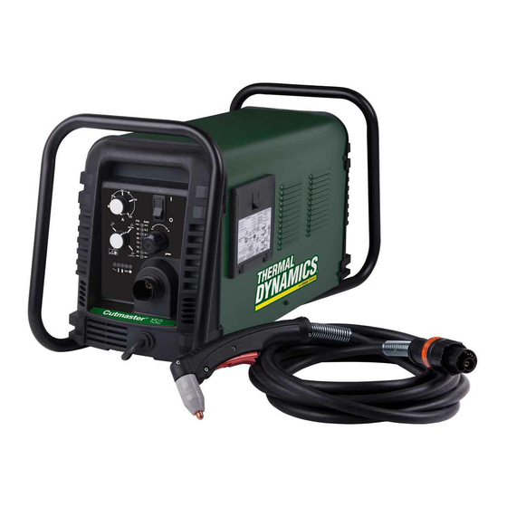
CUTMASTER 152 2.06 Power Supply Features Handle and Leads Wrap Control Panel Torch Leads Receptacle Art # A-08359 Work Cable and Clamp Port for Optional Automation Interface Cable Input Power Selection Filter Assembly Gas Inlet Port Art # A-08360 Input Power Cord INTRODUCTION Manual 0-4987... -
Page 19: Section 2 Torch: Introduction
CUTMASTER 152 SECTION 2 TORCH: 2T.03 Specifications INTRODUCTION A. Torch Configurations 1. Hand/Manual Torch, Models 2T.01 Scope of Manual The hand torch head is at 75° to the torch handle. The hand torches include a torch handle and torch This manual contains descriptions, operating trigger assembly. -
Page 20: 04 Options And Accessories
CUTMASTER 152 2T.05 Introduction to Plasma F. Torch Ratings Manual Torch Ratings A. Plasma Gas Flow Ambient 104° F Plasma is a gas which has been heated to an ex- Temperature 40° C tremely high temperature and ionized so that it Duty Cycle 100% @ 100 Amps @ 400 scfh becomes electrically conductive. - Page 21 CUTMASTER 152 B. Gas Distribution E. Parts - In - Place (PIP) The single gas used is internally split into plasma The torch includes a 'Parts - In - Place' (PIP) circuit. and secondary gases. When the shield cup is properly installed, it closes a switch.
- Page 22 CUTMASTER 152 This Page Intentionally Blank INTRODUCTION 2T-4 Manual 0-4987...
-
Page 23: Section 3 System: Installation
CUTMASTER 152 SECTION 3 SYSTEM: 3.03 Primary Input Power Connections INSTALLATION 3.01 Unpacking CAUTION 1. Use the packing lists to identify and ac- Check your power source for correct voltage count for each item. before plugging in or connecting the unit. Check 2. - Page 24 CUTMASTER 152 B. Connections to Three Phase Input Power A. Connections to Single Phase Input Power WARNING WARNING Disconnect input power from the power supply Disconnect input power from the power supply and input cable before attempting this procedure. and input cable before attempting this procedure. These instructions are for changing the input These instructions are for changing the input power and or cable on the 208/230, 400, 460 VAC...
-
Page 25: Gas Connections
CUTMASTER 152 3.04 Gas Connections NOTE For a secure seal, apply thread sealant to the Connecting Gas Supply to Unit fitting threads, according to the maker's instruc- The connection is the same for compressed air or tions. Do Not use Teflon tape as a thread sealer, as small particles of the tape may break off and high pressure cylinders. - Page 26 CUTMASTER 152 Regulator/Filter Assembly 2-Stage Filter Inlet Port (IN) Regulator Input Outlet Port (OUT) Two Stage Filter Hose Clamp Assembly Gas Supply Hose 1/4 NPT to 1/4” (6mm) Fitting Art # A-07945_AC Optional Two - Stage Filter Installation Using High Pressure Air Cylinders When using high pressure air cylinders as the air supply: 1.
-
Page 27: Section 3 Torch: Installation
2. Put the Function Control switch in the SET If necessary, connect the torch to the Power Sup- position. ply. Connect only the Thermal Dynamics model 3. Place a welding filter lens in front of the SL100 / Manual or SL100 / Mechanical Torch to torch and turn ON the air. - Page 28 CUTMASTER 152 Pinch Block Assembly Square Workpiece A-02585 Mechanical Torch Set - Up 3. The proper torch parts (shield cup, tip, start cartridge, and electrode) must be installed for the type of operation. Refer to Section 4T.07, Torch Parts Selection for details. INSTALLATION 3T-2 Manual 0-4987...
-
Page 29: Section 4 System: Operation
CUTMASTER 152 SECTION 4 SYSTEM: OPERATION 4.01 Front Panel Controls / Features See Illustration for numbering Identification 1. Output Current Control Sets the desired output current. Output settings up to 60 Amps may be used for drag cutting (with the torch tip contacting the workpiece) or higher for standoff cutting. -
Page 30: Preparations For Operation
Check that the torch is properly connected. Only Set Operating Pressure Thermal Dynamics model SL100 / Manual or SL100 1. Place the Power Supply Function Control / Mechanical Torches may be connected to this Power Supply. - Page 31 CUTMASTER 152 Typical Cutting Speeds STANDOFF CutMaster 152 Gas Pressure Settings Cutting speeds vary according to torch output am- perage, the type of material being cut, and operator Leads SL100 SL100 skill. Refer to Section 4T.08 and following for greater Length (Hand Torch) (Mechanized Torch)
- Page 32 CUTMASTER 152 This Page Intentionally Blank OPERATION Manual 0-4987...
-
Page 33: Section 4 Torch: Operation
CUTMASTER 152 2. Remove the Electrode by pulling it straight SECTION 4 TORCH: out of the Torch Head. OPERATION Torch Head 4T.01 Torch Parts Selection Electrode Depending on the type of operation to be done determines the torch parts to be used. Type of operation: Start Cartridge Drag cutting, standoff cutting or gouging... -
Page 34: 02 Cut Quality
CUTMASTER 152 4T.02 Cut Quality Bottom Dross Buildup Molten material which is not blown out of the cut NOTE area and resolidifies on the plate. Excessive dross may require secondary cleanup operations after Cut quality depends heavily on setup and cutting. -
Page 35: 04 Hand Torch Operation
CUTMASTER 152 4T.04 Hand Torch Operation Edge Starting For edge starts, hold the torch perpendicular to the Standoff Cutting With Hand Torch workpiece with the front of the tip near (not touch- ing) the edge of the workpiece at the point where NOTE the cut is to start. - Page 36 CUTMASTER 152 3. Hold the torch away from your body. NOTE 4. Slide the trigger release toward the back When the shield cup is properly installed, of the torch handle while simultaneously there is a slight gap between the shield cup squeezing the trigger.
- Page 37 CUTMASTER 152 Drag Cutting With a Hand Torch Trigger Drag cutting works best on metal 1/4" (6 mm) thick or less. NOTE Trigger Release Drag cutting can only be performed at 60 amps or less. For best parts performance and life, always use the correct parts for the type of opera- tion.
-
Page 38: 05 Gouging
CUTMASTER 152 3. In a portion of the unwanted metal start the 4T.05 Gouging pierce off the cutting line and then continue the cut onto the line. Hold the torch per- pendicular to the workpiece after the pierce WARNING is complete. Be sure the operator is equipped with proper 4. -
Page 39: 06 Mechanized Torch Operation
CUTMASTER 152 4T.06 Mechanized Torch Operation Pressure Setting Even though the setting is within the specified range, Cutting With Mechanized Torch if the torch does not pilot well the pressure may need to be reduced. The mechanized torch can be activated by remote control pendant or by a remote interface device Lead Angle such as CNC. - Page 40 CUTMASTER 152 For optimum smooth surface quality, the travel speed should be adjusted so that only the leading edge of the arc column produces the cut. If the travel speed is too slow, a rough cut will be produced as the arc moves from side to side in search of metal for transfer.
-
Page 41: 07 Parts Selection For Sl100 Torch Cutting
CUTMASTER 152 4T.07 Parts Selection for SL100 Torch Cutting Ohmic Clip Automation Torch Ohmic Clip 9-8224 Manual Torch 9-8259 20-40A Shield Tip: Shield Cap, Machine Cup Body, STANDOFF 40A 9-8245 9-8237 CUTTING 9-8205 Shield Cap, Deflector Shield Cup 9-8206 9-8243 9-8218 9-8208 Drag Shield Cup... -
Page 42: 08 Recommended Cutting Speeds For Sl100 Torch With Exposed Tip
CUTMASTER 152 4T.08 Recommended Cutting Speeds for SL100 Torch With Exposed Tip Type Torch: SL100 With Exposed Tip Type Material: Mild Steel Type Plasma Gas: Air Type Secondary Gas: Single Gas Torch Thickness Output Amperage Speed (Per Minute) Standoff Plasma Gas Press Flow (CFH) Pierce Pierce Height... - Page 43 CUTMASTER 152 Type Torch: SL100 With Exposed Tip Type Material: Mild Steel Type Plasma Gas: Air Type Secondary Gas: Single Gas Torch Thickness Output Amperage Speed (Per Minute) Standoff Plasma Gas Press Flow (CFH) Pierce Pierce Height Inches mm (Cat. No.) Volts(VDC) (Amps) Inches Meters Inches mm psi* Plasma Total** Delay (Sec) Inches mm...
- Page 44 CUTMASTER 152 Type Torch: SL100 With Exposed Tip Type Material: Mild Steel Type Plasma Gas: Air Type Secondary Gas: Single Gas Torch Thickness Output Amperage Speed (Per Minute) Standoff Plasma Gas Press Flow (CFH) Pierce Pierce Height Inches mm (Cat. No.) Volts(VDC) (Amps) Inches Meters Inches mm psi* Plasma Total** Delay (Sec) Inches...
- Page 45 CUTMASTER 152 Type Torch: SL100 With Exposed Tip Type Material: Mild Steel Type Plasma Gas: Air Type Secondary Gas: Single Gas Torch Thickness Output Amperage Speed (Per Minute) Standoff Plasma Gas Press Flow (CFH) Pierce Pierce Height Inches mm (Cat. No.) Volts(VDC) (Amps) Inches Meters Inches mm psi* Plasma Total** Delay (Sec) Inches...
- Page 46 CUTMASTER 152 Type Torch: SL100 With Exposed Tip Type Material: Mild Steel Type Plasma Gas: Air Type Secondary Gas: Single Gas Torch Thickness Output Amperage Speed (Per Minute) Standoff Plasma Gas Press Flow (CFH) Pierce Pierce Height Inches mm (Cat. No.) Volts(VDC) (Amps) Inches Meters Inches mm psi* Plasma Total** Delay (Sec) Inches...
-
Page 47: 09 Recommended Cutting Speeds For Sl100 Torch With Shielded Tip
CUTMASTER 152 4T.09 Recommended Cutting Speeds for SL100 Torch With Shielded Tip Type Torch: SL100 With Shielded Tip Type Material: Mild Steel Type Plasma Gas: Air Type Secondary Gas: Single Gas Torch Thickness Output Amperage Speed (Per Minute) Standoff Plasma Gas Press Flow (CFH) Pierce Pierce Height... - Page 48 CUTMASTER 152 Type Torch: SL100 With Shielded Tip Type Material: Mild Steel Type Plasma Gas: Air Type Secondary Gas: Single Gas Torch Thickness Output Amperage Speed (Per Minute) Standoff Plasma Gas Press Flow (CFH) Pierce Pierce Height Inches mm (Cat. No.) Volts(VDC) (Amps) Inches Meters Inches mm psi* Plasma Total** Delay (Sec) Inches mm...
- Page 49 CUTMASTER 152 Type Torch: SL100 With Shielded Tip Type Material: Mild Steel Type Plasma Gas: Air Type Secondary Gas: Single Gas Torch Thickness Output Amperage Speed (Per Minute) Standoff Plasma Gas Press Flow (CFH) Pierce Pierce Height Inches mm (Cat. No.) Volts(VDC) (Amps) Inches Meters Inches psi* Plasma Total** Delay (Sec) Inches mm...
- Page 50 CUTMASTER 152 Type Torch: SL100 With Shielded Tip Type Material: Mild Steel Type Plasma Gas: Air Type Secondary Gas: Single Gas Torch Thickness Output Amperage Speed (Per Minute) Standoff Plasma Gas Press Flow (CFH) Pierce Pierce Height Inches (Cat. No.) Volts(VDC) (Amps) Inches Meters Inches psi* Plasma Total** Delay (Sec) Inches mm 0.250 6.4...
- Page 51 CUTMASTER 152 Type Torch: SL100 With Shielded Tip Type Material: Mild Steel Type Plasma Gas: Air Type Secondary Gas: Single Gas Torch Thickness Output Amperage Speed (Per Minute) Standoff Plasma Gas Press Flow (CFH) Pierce Pierce Height Inches (Cat. No.) Volts(VDC) (Amps) Inches Meters Inches psi* Plasma Total** Delay (Sec) Inches mm 0.250 6.4...
-
Page 52: Patent Information
CUTMASTER 152 PATENT INFORMATION Plasma Cutting Torch Patents The following parts are covered under U.S. and Foreign Patents as follows: Catalog # Description Patent(s) 9-8215 Electrode US Pat No(s) 6163008; 6987238 Other Pat(s) Pending 9-8213 Cartridge US Pat No(s) 6903301; 6717096; 6936786; 6703581;... - Page 53 CUTMASTER 152 Catalog # Description Patent(s) 9-8245 Shield Cap US Pat No(s) 6914211; D496951 Other Pat(s) Pending The following parts are also licensed under U.S. Patent No. 5,120,930 and 5,132,512: Catalog # Description 9-8235 Shield Cap 9-8236 Shield Cap 9-8237 Shield Cup 9-8238 Shield Cap...
- Page 54 CUTMASTER 152 This Page Intentionally Blank OPERATION 4T-22 Manual 0-4987...
-
Page 55: Section 5 System: Service
CUTMASTER 152 SECTION 5 SYSTEM: SERVICE 5.01 General Maintenance Maintain more often Warning! if used under severe Disconnect input power before maintaining. conditions Each Use Visual check of torch tip and electrode Weekly Visually inspect the cables and leads. Replace as needed Visually inspect the torch body tip, electrode, start cartridge and shield cup 3 Months... -
Page 56: Maintenance Schedule
3. Metal too thick. ment. 4. Worn torch parts 5. Cutting current too low. Daily Operational Checks or Every Six Cutting 6. Non - Genuine Thermal Dynamics Hours: parts used 7. Incorrect gas pressure Check torch consumable parts, replace if damaged or worn. -
Page 57: Fault Indicator
CUTMASTER 152 5.04 Fault Indicator At initial power up, two lights will temporarily illu- minate for 2-3 seconds to show the version of software used. To determine the first digit, count the function indicators left to right, 1 through 5. To determine the second digit count the pressure indicators, reading from bottom to top, 0 through 7. -
Page 58: Basic Troubleshooting Guide
CUTMASTER 152 5.05 Basic Troubleshooting Guide WARNING There are extremely dangerous voltage and power levels present inside this unit. Do not attempt to diagnose or repair unless you have had training in power electronics measurement and troubleshooting techniques. Problem - Symptom Possible Cause Recommended Action ON / OFF Switch 1. - Page 59 CUTMASTER 152 Problem - Symptom Possible Cause Recommended Action FAULT & 80 PSI 1. Torch shield cup is loose. 1. Tighten shield cup by hand. Do not overtighten. indicators flashing. 2. Torch tip, electrode or starter 2. Turn OFF power supply. Remove shield cup. Install missing Gas flow is cycling parts. cartridge missing. ON and OFF. 3. Turn OFF power supply. Bleed down system pressure. 3. Torch starter cartridge is stuck. Remove shield cup, tip and starter cartridge.
-
Page 60: Power Supply Basic Parts Replacement
CUTMASTER 152 5.06 Power Supply Basic Parts C. Filter Element Assembly Replacement Replacement The Filter Element Assembly is in the rear panel. For better system performance, the filter element should be checked per the Maintenance Schedule (Subsection 5.02), and either cleaned or replaced. WARNING 1. - Page 61 CUTMASTER 152 Optional Single-Stage Filter Element 5. Remove the fitting from the filter element as- sembly by inserting a 6 mm hex wrench into Replacement the internal hex fitting and turning it counter These instructions apply to power supplies where the clock-wise (left).
- Page 62 CUTMASTER 152 Optional Two-Stage Filter Element Replacement The Two-Stage Air Filter has two Filter Elements. When the Filter Elements become dirty the Power Supply will continue to operate but cut quality may become unac- ceptable. Refer to Section 6, Parts List, for replacement filter element catalog number.
-
Page 63: Section 5 Torch: Service
CUTMASTER 152 SECTION 5 TORCH: SERVICE Upper Groove 5T.01 General Maintenance with Vent Holes Must Remain Open NOTE Upper O-Ring in Correct Groove Refer to Previous "Section 5 System" for common and fault indicator descriptions. Threads Cleaning Torch Lower O-Ring Art # A-03725 Torch Head O-Ring Even if precautions are taken to use only clean air... -
Page 64: 02 Inspection And Replacement Of Consumable Torch Parts
CUTMASTER 152 5T.02 Inspection and Replacement 4. Remove the tip. Check for excessive wear (indi- cated by an elongated or oversized orifice). Clean of Consumable Torch Parts or replace the tip if necessary. Good Tip Worn Tip WARNING Disconnect primary power to the system before disassembling the torch or torch leads. -
Page 65: Section 6: Parts Lists
CUTMASTER 152 SECTION 6: PARTS LISTS 6.01 Introduction A. Parts List Breakdown The parts list provide a breakdown of all replaceable components. The parts lists are arranged as follows: Section "6.03 Power Supply Replacement" Section "6.04 Replacement Power Supply Parts" Section "6.05 Options and Accessories"... -
Page 66: Replacement Power Supply Parts
CUTMASTER 152 6.04 Replacement Power Supply Parts Description Catalog # Regulator 9-0115 Filter Assembly Replacement Element 9-0116 Input Power Cord for 208 / 230 V Power Supply 9-0191 460/600V Power Supply 9-0209 6.05 Options and Accessories Description Catalog # Single - Stage Filter Kit (includes Filter & Hose) 7-7507 Replacement Filter Body 9-7740... -
Page 67: Replacement Parts For Hand Torch
CUTMASTER 152 6.06 Replacement Parts for Hand Torch Item # Description Catalog # Torch Handle Replacement Kit (includes items No. 2 & 3) 9-7030 Trigger Assembly Replacement Kit 9-7034 Handle Screw Kit (5 each, 6-32 x 1/2” cap screw, and wrench) 9-8062 Torch Head Assembly Replacement Kit (includes items No. -
Page 68: Replacement Parts - For Machine Torches With Unshielded Leads
CUTMASTER 152 6.07 Replacement Parts - for Machine Torches with Unshielded Leads Item No. Qty Description Catalog No. Torch Head Assembly without leads (includes items 2, 3, and 14) 9-8220 Large O-ring 8-3487 Small O-ring 8-3486 PIP Switch Kit 9-7036 Unshielded Automated Leads Assemblies with ATC connectors 5 - foot / 1.5 m Leads Assembly with ATC connector 4-7850... - Page 69 CUTMASTER 152 5 & 6 A-07994_AB Manual 0-4987 PARTS LIST...
-
Page 70: Replacement Shielded Machine Torch Leads Assemblies
CUTMASTER 152 6.08 Replacement Shielded Machine Torch Leads Assemblies Item No. Qty Description Catalog No. Mechanized Shielded Leads Assemblies with ATC Connectors 5 - foot / 1.5 m Leads Assembly with ATC Connector 4-7846 10 - foot / 3.05 m Leads Assembly with ATC Connector 4-7847 25 - foot / 7.6 m Leads Assembly with ATC Connector 4-7848... -
Page 71: Torch Consumable Parts (Sl100)
CUTMASTER 152 6.09 Torch Consumable Parts (SL100) Ohmic Clip Automation Torch Ohmic Clip 9-8224 Manual Torch 9-8259 20-40A Shield Tip: Shield Cap, Machine Cup Body, STANDOFF 40A 9-8245 9-8237 CUTTING 9-8205 Shield Cap, Deflector Shield Cup 9-8206 9-8243 9-8218 9-8208 Drag Shield Cup 9-8235 50-60A... - Page 72 CUTMASTER 152 This Page Intentionally Blank PARTS LIST Manual 0-4987...
-
Page 73: Appendix 1: Sequence Of Operation (Block Diagram
CUTMASTER 152 APPENDIX 1: SEQUENCE OF OPERATION (BLOCK DIAGRAM) ACTION: ACTION: ACTION: ACTION: RUN / Rapid Auto Restart / ON / OFF switch to ON Close external RUN / SET / LATCH disconnect switch. Rapid Auto Restart / switch to RUN RESULT: SET / LATCH switch RESULT:... -
Page 74: Appendix 2: Data Tag Information
CUTMASTER 152 APPENDIX 2: DATA TAG INFORMATION Manufacturer's Name and/or West Lebanon, NH USA 03784 Logo, Location, Model and Revision Level, Serial Number M odel : and Production Code Dat e of M f r : Made in USA Type of Power Regulatory Standard Covering 1/ 3 Supply (Note 1) -
Page 75: Appendix 3: Torch Pin - Out Diagrams
CUTMASTER 152 APPENDIX 3: TORCH PIN - OUT DIAGRAMS A. Hand Torch Pin - Out Diagram ATC Female Receptacle ATC Male Connector Front View Front View Negative / Negative / Plasma Plasma 8 - Open 8 - Ground 4 - Green / Switch 4 - Switch 3 - Switch... -
Page 76: Appendix 4: Torch Connection Diagrams
CUTMASTER 152 APPENDIX 4: TORCH CONNECTION DIAGRAMS A. Hand Torch Connection Diagram Torch: SL60 / SL100 Hand Torch Leads: Torch Leads with ATC Connector Power Supply: with ATC Receptacle Male ATC Leads ATC Female Connector Receptacle Power Torch Torch Supply Head Leads Black... - Page 77 CUTMASTER 152 This Page Intentionally Blank Manual 0-4987 APPENDIX...
-
Page 78: Appendix 5: System Schematic, 208/460V Units
CUTMASTER 152 APPENDIX 5: SYSTEM SCHEMATIC, 208/460V UNITS PRI 3 PRI 3 PRI 4 PRI 4 BIAS SUPPLY PRI 2 PRI 2 PRI 2 PRI 2 INRUSH +12VDC RESISTORS PRI 1 PRI 1 PRI 1 PRI 1 MTH1 MTH1 MTH2 MTH2 /INRUSH +12VDC... - Page 79 Date: Date: Date: ECO B1357 RWH 03/31/09 Information Proprietary to THERMAL DYNAMICS CORPORATION. Information Proprietary to THERMAL DYNAMICS CORPORATION. Information Proprietary to THERMAL DYNAMICS CORPORATION. JANUARY 31, 2008 Not For Release, Reproduction, or Distribution without Written Consent. Not For Release, Reproduction, or Distribution without Written Consent.
-
Page 80: Appendix 6: System Schematic, 600V Units
CUTMASTER 152 APPENDIX 6: SYSTEM SCHEMATIC, 600V UNITS PRI 4 PRI 4 PRI 3 PRI 3 BIAS SUPPLY PRI 2 PRI 2 PRI 2 PRI 2 INRUSH +12VDC RESISTORS PRI 1 PRI 1 PRI 1 PRI 1 MTH1 MTH1 MTH2 MTH2 CHOKE /INRUSH... - Page 81 ECO B1611 05/05/09 Date: Date: Date: Information Proprietary to THERMAL DYNAMICS CORPORATION. Information Proprietary to THERMAL DYNAMICS CORPORATION. Information Proprietary to THERMAL DYNAMICS CORPORATION. MARCH 30, 2009 Not For Release, Reproduction, or Distribution without Written Consent. Not For Release, Reproduction, or Distribution without Written Consent.
-
Page 82: Appendix 7: Publication History
CUTMASTER 152 APPENDIX 7: Publication History Cover Date Rev. Change(s) May 30, 2008 Manual released. June 23, 2008 Updated with new Cut Charts, updated system schematic per ECOB935 and added 460V version per ECOB939. Nov. 19, 2008 Updated system schematic. Jan 27, 2009 Corrected art sizing in section 3 to show missing information per ECOB1248. - Page 83 This Page Intentionally Blank...
- Page 84 Printed in: Mexico U.S. Customer Care: 800-426-1888 / 800-535-0557 Canada Customer Care: 905-827-4515 / 800-588-1714 • International Customer Care: 940-381-1212 / 940-483-8178 www.thermal-dynamics.com • A Global Cutting & Welding Market Leader ™ W O R L D H E A D Q U A R T E R S : 1 6 0 5 2 S w i n g l e y R i d g e R o a d , S u i t e 3 0 0 •...
Need help?
Do you have a question about the 152 CUTMASTER and is the answer not in the manual?
Questions and answers