
Related Manuals for Thermal Dynamics CE PAK Master 150XL


Summary of Contents for Thermal Dynamics CE PAK Master 150XL
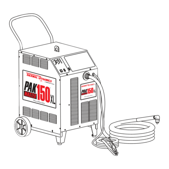
- Page 1 PLASMA CUTTING POWER SUPPLY ® CE PAK Master 150XL™ A-03044 Service Manual September 15, 2003 Manual No. 0-2728...
- Page 3 Manufacturer assumes no liability for its use. Plasma Cutting Power Supply ® CE Pak Master 150XL Service Manual Number 0-2728 Published by: Thermal Dynamics Corporation 82 Benning Street West Lebanon, New Hampshire, USA 03784 (603) 298-5711 www.thermal-dynamics.com Copyright 1999 by Thermal Dynamics Corporation All rights reserved.
-
Page 4: Table Of Contents
TABLE OF CONTENTS SECTION 1: GENERAL INFORMATION ....................1-1 1.01 Notes, Cautions and Warnings ..............1-1 1.02 Important Safety Precautions ............... 1-1 1.03 Publications ....................1-2 1.04 Note, Attention et Avertissement ..............1-3 1.05 Precautions De Securite Importantes ............1-3 1.06 Documents De Reference ................ - Page 5 TABLE OF CONTENTS (continued) SECTION 6: PARTS LISTS ........................6-1 6.01 Introduction ....................6-1 6.02 Ordering Information ................... 6-1 6.03 Major External Replacement Parts .............. 6-2 6.04 Access Panel Replacement Parts ............... 6-3 6.05 Left Side Center Chassis Replacement Parts ..........6-4 6.06 Right Side Center Chassis Replacement Parts ...........
-
Page 7: General Information
SECTION 1: GASES AND FUMES GENERAL INFORMATION Gases and fumes produced during the plasma cutting process can be dangerous and hazardous to your health. 1.01 Notes, Cautions and Warnings • Keep all fumes and gases from the breathing area. Throughout this manual, notes, cautions, and warnings Keep your head out of the welding fume plume. -
Page 8: Publications
• Wear dry gloves and clothing. Insulate yourself from the work piece or other parts of the welding PLASMA ARC RAYS circuit. • Repair or replace all worn or damaged parts. Plasma Arc Rays can injure your eyes and burn your skin. •... -
Page 9: Note, Attention Et Avertissement
6. ANSI Standard Z49.2, FIRE PREVENTION IN THE USE ATTENTION OF CUTTING AND WELDING PROCESSES, obtain- able from American National Standards Institute, 1430 Broadway, New York, NY 10018 Toute procédure pouvant résulter l’endommagement du matériel en cas de non- 7. AWS Standard A6.0, WELDING AND CUTTING CON- respect de la procédure en question. - Page 10 • Eloignez toute fumée et gaz de votre zone de respira- • Ne touchez jamais une pièce “sous tension” ou “vive”; tion. Gardez votre tête hors de la plume de fumée portez des gants et des vêtements secs. Isolez-vous provenant du chalumeau. de la pièce de travail ou des autres parties du circuit de soudage.
-
Page 11: Documents De Reference
ultra-violets très forts. Ces rayons d’arc nuiront à vos 1.06 Documents De Reference yeux et brûleront votre peau si vous ne vous protégez pas correctement. Consultez les normes suivantes ou les révisions les plus récentes ayant été faites à celles-ci pour de plus amples •... - Page 12 9. Norme 70 de la NFPA, CODE ELECTRIQUE NA- TIONAL, disponible auprès de la National Fire Pro- tection Association, Batterymarch Park, Quincy, MA 02269 10. Norme 51B de la NFPA, LES PROCÉDÉS DE COUPE ET DE SOUDAGE, disponible auprès de la National Fire Protection Association, Batterymarch Park, Quincy, MA 02269 11.
-
Page 13: Declaration Of Conformity
Rigorous testing is incorporated into the manufacturing process to ensure the manufactured product meets or exceeds all design specifications. Thermal Dynamics has been manufacturing products for more than 30 years, and will continue to achieve excellence in our area of manufacture. -
Page 14: Statement Of Warranty
None Warranty repairs or replacement claims under this limited warranty must be submitted by an authorized Thermal Dynamics® repair facility within thirty (30) days of the repair. No transportation costs of any kind will be paid under this warranty. Transportation charges to send products to an authorized warranty repair facility shall be the responsibility of the customer. -
Page 15: Introduction
C. Customer/Operator Responsibilities It is the customer/operator's responsibility to maintain the equipment and peripheral accessories provided by Thermal Dynamics in good operating order in accordance with the procedures outlined in the Operating Manual, and to protect the equipment from accidental or mali- cious damage. - Page 16 INTRODUCTION Manual 0-2728...
-
Page 17: Description
SECTION 3: DESCRIPTION 3.01 Scope of Manual The information in this section has two purposes: • To familiarize the service technician with the capa- bilities and limitations of the equipment, • To provide an overall understanding which will al- low the technician, in turn, to properly train customer's operating personnel. -
Page 18: Specifications/Design Features
3.03 Specifications/Design Features Power Supply Duty Cycle A. Power Supply Specifications Ambient 104° F 104° F Temperature (40° C) (40° C) The following specifications apply to the Power Supply only: 100% Duty Cycle 120 Amps n/a Amps 1. Front Panel Controls Current DC Voltage 128 vdc... -
Page 19: Power Supply Options And Accessories
15. Weight 3.04 Power Supply Options and Accessories Power Supply with Torch: 275 lbs (125 kg) Shipping Weight: 350 lbs (158.8 kg) The following accessories are available for the Power Supply. Refer to Section 6, Parts Lists, for part numbers 16. - Page 20 B. Input and Output Power 2. Gas Pressure Interlock A pressure switch acts as an interlock for the The unit converts AC input power to DC power for the plasma gas supply. If the plasma gas supply pres- main cutting arc. The negative output is connected to sure falls below minimum requirements the pres- the torch electrode through the negative torch lead, and sure switch will open, shutting off the power to...
-
Page 21: Service Troubleshooting
C. Power Supply Cleaning SECTION 4: To clean the unit, open the enclosure and use a vacuum SERVICE cleaner to remove any accumulated dirt and dust. The TROUBLESHOOTING unit should also be wiped clean. If necessary, solvents that are recommended for cleaning electrical apparatus may be used. - Page 22 5. Remove Coolant Reservoir lid and install new coolant and deionizer bag. To accurately measure the coolant conductivity it is recommended to use a Conductivity Sensor simi- 6. Reinstall the right side panel. lar to Thermal Dynamics Model TDS-73 (Catalog # 7-2844). SERVICE TROUBLESHOOTING Manual 0-2728...
-
Page 23: System Theory
4.03 System Theory Logic PC B oard The Cutting System is designed for hand cutting and simple mechanized operation using the torch control bulk- Indicator Meaning head as the interface. Torch Switch Enable - When ON A. Logic PC Board Functions (start) indicates torch switch is pressed. -
Page 24: Common Operating Problems
4.04 Common Operating Problems Gate Drive P C B oards Indicator Meaning WARNINGS Power Enable - When ON PWM Enable received from the Logic Disconnect primary power at the source before dis- PC Board. assembling the power supply, torch, or torch leads. Reset - Normally ON, goes out Frequently review the Important Safety Precau- when torch switch is pressed. -
Page 25: Troubleshooting Guide - General Information
"High speed dross" usually forms g. Non-Genuine Thermal Dynamics parts used a narrow bead along the bottom of the cut edge and is very difficult to remove. When cutting a trouble- 4.05 Troubleshooting Guide -... -
Page 26: Circuit Fault Isolation
Subsection 4.09 includes specific test procedures and LED 4.06 Circuit Fault Isolation status identification tables. The subsection is referenced by the troubleshooting guide for the specific test to be This section is used before troubleshooting to help iso- performed. late the defective circuit, identify symptoms, and test the unit for proper operation. -
Page 27: Main Input And Internal Power Problems
Set the Power Supply RUN/SET switch to the RUN posi- 4.07 Main Input and Internal Power tion and note the following: Problems • Gas Indicator goes OFF NOTES • Gas flow stops The Input PC Board has a neon light on the upper NOTE left hand corner. - Page 28 5. Actual input voltage is not within the specified range. 5. Defective Logic PC Board This unit is designed to be operated from 380-415V, 3- On Logic PC Board remove J4 and J2 connectors Phase input power. a. If TEMP Indicator stays ON then replace Logic a.
-
Page 29: Pilot Arc Problems
3. Low or No Coolant Flow H. AC indicator ON; Gas flows; GAS and DC indica- tors ON; Arc in torch without pressing torch a. Check for proper coolant level. If low, fill to switch; D26 (Torch Switch Enable) on Logic PCB correct level. - Page 30 2. Faulty Logic PC Board 5. Faulty Torch or Leads (see note above) a. Measure for 120VAC at the Logic PC Board con- a. Remove wire 15 from Pilot Output PC Board nector J2-1 and J2-4. terminal E24. • If voltage is present, then check connections b.
-
Page 31: Main Cutting Arc Problems
D. AC indicator ON; Gas flows; GAS and DC indica- 4.09 Main Cutting Arc Problems tors ON; Spark at gap on CD PC Board and CD enable indicator (D25) on Logic PC Board ON; No NOTE arc or intermittent arc in torch Refer to the Appendix Pages for PC Board Lay- 1. -
Page 32: Test Procedures
B. When operating at amperages over 35 amps the 5. Electrostatic discharge can damage printed circuit amperage drops off after main cutting arc initiates board assemblies. Transport printed circuit boards in proper anti-static shielded packages. Use proper Check whether Drag indicator (D31) on the Logic PC grounding techniques with wrist strap before handling Board is ON when the torch tip comes in contact with printed circuit boards. - Page 33 4. Pull the top of the Side Panel out and then lift up to remove the panel from the Power Supply a short dis- A-00307 tance (see NOTE). NOTE 0.75 There is a ground wire connection to the Side Panel on the inside of the unit.
- Page 34 D. Input PC Board /Input Bridge Rectifier Test E. Main Contactor (MC1) Test Locate the Input PC Board and check for shorted input Reconnect power and observe proper start-up procedure. diode. Indicator D47 on the Logic PC Board should be ON. If indicator D47 is OFF there is no voltage to the Power NOTE Supply or an overvoltage condition exists.
- Page 35 H. Temperature Circuit Test 8. Check status of the TEMP Indicator. If Indicator is OFF, remove power and replace the upper or lower The Power Supply has seven temperature sensing pair of FET/Heatsink Assemblies. switches. 9. Repeat steps 1-8 for each FET Assembly. •...
- Page 36 2. Measure for 115 VAC from J2-2 to J17-3 at the Logic 1. No DC Output PC Board. An open circuit voltage of approximately 280 to 325 If voltage is not correct replace Logic PC Board. vdc (depending on input power selected) is produced when switching transistors in the FET/Heatsink As- 3.
- Page 37 2. FET/Heatsink Output Diode Checks Place the meter (+) lead on drain lead of Q1 and meter (-) lead on source lead of Q1. The meter Remove input power from the unit. should indicate >100K ohms. Isolate each FET/Heatsink Assembly by removing the NOTES red wire #12 at E18 and the black wire #11 at E17 on Make measurements near the body of each...
- Page 38 5. FET Output Rectifier Check e. Place the meter (+) lead on E19 and the meter (-) lead on E17 of the FET/Heatsink Assembly to NOTE check the output rectifier reverse bias. The meter should indicate 'OL' using the diode function or Refer to the Appendix Pages for PC Board Lay- 100K ohms using the ohms function.
-
Page 39: Replacement Procedures
2. Unroll the rest of the band and peel the liner from SECTION 5: the copper foil at the opposite end. REPLACEMENT 3. Attach the copper foil to a convenient and exposed electrical ground. PROCEDURES 4. Connect the equipment primary cable ground to the same electrical ground as the wrist strap. -
Page 40: Major External Parts Replacement
7. Install the replacement Side Panel by reversing the above procedure doing the following: WARNING a. Reconnect the ground wire to the Side Panel, if disconnected. Disconnect primary power from the source before opening or disassembling the power supply. Make b. -
Page 41: Access Panel Parts Replacement
E. Front Panel Replacement 3. Squeeze the top and bottom of the switch while pulling it out of the Access Panel. 1. Remove the Left and Right Side Panels per Sec- 4. Install the replacement ON/OFF Switch by revers- tion 5.04-A. ing the above procedure. -
Page 42: Left Side Center Chassis Parts Replacement
E. Pot/LED PC Board Assembly Replacement 5.06 Left Side Center Chassis Parts Replacement 1. Turn the CURRENT adjustment fully counter clockwise and note the location of the pointer on NOTE the knob. Refer to Section 6.05 for parts list and overall de- 2. - Page 43 C. Input PC Board Assembly Replacement D. Input Bridge Rectifier Replacement 1. Remove the Left Side Panel per Section 5.04-A. 1. Remove the Left Side Panel per Section 5.04-A. 2. Disconnect all cable lug connections to Input 2. Remove the Input PC Board per Section 5.06-C. Board, removing star washers and nuts where 3.
- Page 44 G. Logic PC Board Replacement 3 . Remove the four screws securing the Gate Drive PC Board to the four standoffs. 1. Remove the Left Side Panel per section 5.04-A. 4. Reinstall the replacement Gate Drive PCB Assem- 2. Carefully remove all cable connections from the bly by reversing the above procedure.
-
Page 45: Right Side Center Chassis Parts Replacement
5. Remove the two screws securing the Heatsink 5.07 Right Side Center Chassis Mounting Bracket to the chassis. Parts Replacement 6. To remove the Mounting Bracket lift up on the NOTE top FET/Heatsink Assembly and push down on the bottom FET/Heatsink Assembly in the middle Refer to Section 6.06 for parts list and overall de- where the two FET/Heatsink Assemblies come tail drawing. - Page 46 C. Pilot Resistor (R1 & R2) Replacement F. Coolant Filter Replacement NOTE 1. Remove Right Side Panel per Section 5.04-A. This unit has two Pilot Resistors. The replacement 2. Remove the two coolant hose connections to the instructions are the same for both. Filter Assembly.
- Page 47 c. Remove the Coolant Reservoir Cap then re- H. In-Line Coolant Filter Assembly move the Deionizer Basket and Deionizer Bag Replacement from the Coolant Reservoir filler hole. 1. Remove the Right Side Panel per Section 5.04-A. 3. Disconnect the Coolant Supply Hose output con- nection from the bottom of the reservoir.
- Page 48 Flow Switch Assembly (FS1) Replacement J. Output Inductor Assembly (L1 & L2) Replacement 1. Remove the Right Side Panel per Section 5.04-A. NOTES CAUTION There are two Output Inductors in this unit. Re- placement instructions are the same for both. Handle and dispose of the used coolant per recom- The Output Inductor(s) are located behind the mended procedures.
- Page 49 10. Locate the two nuts on the base which secure the 2. Drain the coolant from the Coolant Reservoir as reservoir panel to the base, then remove nuts. follows: NOTE a. Remove Reservoir Cap from Reservoir. It may be necessary to disconnect some wiring in b.
- Page 50 10. Carefully remove all wire connections to the FET 4. Carefully note wiring connections, then discon- PCB Assembly noting the location of each per the nect wires. following chart: 5. Install replacement Fan(s) by reversing the above steps, noting the following: FET PCB Cable # a.
-
Page 51: Base Parts Replacement
N. CD Coil Assembly (T4) Replacement NOTE Prior to removal, note the location and orientation of the CD Coil Assembly and all its connections. 1. Remove the Left and Right Side Panels per Sec- Screws tion 5.04-A. 2. Remove the Top Panel per Section 5.04-C. Axle 3. - Page 52 D. Main Contactor Assembly (W) Replacement c. Attach the main harness wires #4 & #5 to the inner prong of L1 & L2 respectively of the main NOTE contactor. The Main Contactor was located in the Base on d. Connect cables 1, 2, and 3 to T1, T2, and T3 earlier units and on the Center Chassis for current respectively.
- Page 53 F. Fan Assembly Only Replacement b. Install check valve with the flow marking to- wards the bottom (as shown above). 1. Remove Motor/Fan/Pump Assembly from unit c. Use thread sealant on all pipe threads (Loctite per procedure in 5.09-E. thread sealant #565, or equivalent). 2.
-
Page 54: Rear Panel Parts Replacement
g. Remove the four screws securing each Regu- 5.09 Rear Panel Parts Replacement lator to the rear panel and remove Regulators. NOTE 4. The EMC Filter Assembly must be removed from the Rear Panel as follows: Refer to Section 6.08 for parts list and overall de- tail drawing. - Page 55 7. To install replacement rear panel, reverse the 4. Remove the Pressure Switch, if applicable. above procedure. 5. Note the orientation of the Solenoid Valve Assem- C. Pressure Switch (PS1) Replacement bly then remove the Solenoid(s) from the two inch brass regulator fitting(s).
- Page 56 3. Remove the four screws securing the Regulator to the Rear Panel. 4. Pull the Air Line Regulator away from the Rear Panel far enough to disconnect the plumbing joint Filter between the Reducer and Elbow Fitting. 5. Remove the Regulator from the 2 inch brass nipple Nomex Shield connected to the Solenoid Assembly.
-
Page 57: Parts Lists
SECTION 6: PARTS LISTS 6.01 Introduction A. Parts List Breakdown The parts lists provide a breakdown of all replaceable components. Parts Lists are organized as follows: Section 6.03 Major External Replacement Parts Section 6.04 Access Panel Replacement Parts Section 6.05 Left Side Center Chassis Replacement Parts Section 6.06 Right Side Center Chassis Replacement Parts... -
Page 58: Major External Replacement Parts
6.03 Major External Replacement Parts Item # Description Catalog # Right Side Panel With Labels 9-7819 Left Side Panel With Labels 9-7818 Front Panel With Labels 9-7816 Rear Panel 9-7820 Top Panel Top Panel for Units Revision I or earlier 9-7817 Top Panel for Units Revision J or later 9-7797... -
Page 59: Access Panel Replacement Parts
6.04 Access Panel Replacement Parts Item # Description Catalog # Assembly, POT/LED PCB Pot/LED Assembly for Units Revision H or earlier 9-7014 Pot/LED Assembly for Units Revision I or later 9-8004 RUN/SET Switch, SPST 9-1042 ON/OFF Switch, DPST 8-3258 Knob, CURRENT Control With Foam Seal 9-8007 DZUS Stud 9-4346... -
Page 60: Left Side Center Chassis Replacement Parts
6.05 Left Side Center Chassis Replacement Parts Item # Description Catalog # Fuse Block, 9-5562 Fuse, 5 AMP, 600V, Delay 10-2274 Input PC Board Assembly 9-7813 Bridge Rectifier Assembly, 110A 3PH 9-7824 Bridge Rectifier, 110A 3PH 9-7800 Thermal Pad, QIII, Input Module Thermostat, Closes @ 80°... - Page 61 A-02580 Manual 0-2728 PARTS LISTS...
-
Page 62: Right Side Center Chassis Replacement Parts
6.06 Right Side Center Chassis Replacement Parts Item # Description Catalog # Pilot/Output PC Board Assembly 9-7809 Relay, DPST, 25A Max, 120 VAC (Coolant Motor Relay) 8-3390 Resistor R1,R2 9-5843 Inductor, Pilot 9-7801 CD PC Board Assembly 9-7814 Coolant Filter 8-4276 Coolant Reservoir 9-5948... - Page 63 A-02275 NOTE: Parts may differ slightly from illustration Manual 0-2728 PARTS LISTS...
-
Page 64: Base Replacement Parts
6.07 Base Replacement Parts Item # Description Catalog # Wheel 8-5579 Axle 9-7891 Support Leg 9-7892 Transformer, Auxiliary (220,395,460) 9-7802 Fuse, 5A, 250V Delay MDL-5 (in Torch Spare Parts Kit) 9-8109 Main Contactor (Location on earlier units) 9-1244 Refer to Section 6.05 for location on current units Fan, Medium Pressure, 8 inch (203 mm) Diameter 9-7893 Motor, 1/3 HP, 1425/1725 RPM, 115/230 V, 50/60 Hz... - Page 65 23x4274 A-02278 Manual 0-2728 PARTS LISTS...
-
Page 66: Rear Panel Replacement Parts
6.08 Rear Panel Replacement Parts Item # Description Catalog # Handle With Screws 9-7822 Pressure Switch, 35 psi (2.4 bar) 9-1044 Valve, Solenoid 1/8 NPT SOL1, SOL2 8-3370 Air Regulator/Filter Assembly Air Line Regulator 9-7514 Pressure Gauge 9-1045 Panel Mounting Nut 9-5804 Bracket, Regulator Mounting 9-7589... - Page 67 A-02387 Manual 0-2728 6-11 PARTS LISTS...
-
Page 68: Options And Accessories
6.09 Options and Accessories Description Catalog # Two Stage Air Line Filter Kit 7-7502 Replacement Elements First Stage 9-1021 Second Stage 9-1022 Mounting Bracket 9-7535 CNC Interface Control Cable - Used With Shielded PCM Machine Torch 25 ft (7.6 m) 8-5557 50 ft (15.2 m) 8-5558... -
Page 69: Appendix 1: Input Wiring Requirements
APPENDIX 1: INPUT WIRING REQUIREMENTS Input Power Input Current Suggested Sizes (See Notes) Voltage Freq. 3-Ph 3-Ph Fuse (Amps) Wire (mm (Volts) (Hz) (kVA) (Amps) 3-Ph 3-Ph 50/60 29.0 50/60 29.5 Line Voltages with Suggested Circuit Protection and Wire Sizes Based on National Electric Code and Canadian Electrical Code NOTES Refer to Local and National Codes or local authority having jurisdiction for proper wiring requirements. -
Page 70: Appendix 2: Sequence Of Operation (Block Diagram
APPENDIX 2: SEQUENCE OF OPERATION (BLOCK DIAGRAM) ACTION ACTION ACTION ACTION ON/OFF switch Close external RUN/SET switch RUN/SET switch to ON. disconnect switch. to RUN. to SET. RESULT RESULT RESULT RESULT AC indicator blinks for 8 Power to system. Gas flow stops. Gas solenoid open, seconds then steady on. -
Page 71: Appendix 3: Pot/Led Pc Board Layout
APPENDIX 3: POT/LED PC BOARD LAYOUT A-01206 Pot/LED PC Board Signals J14-1 +10 vdc from Logic PC Board (J3-7) - Potentiometer High J14-2 Current Control to Logic PC Board (J3-8) - Potentiometer Wiper J14-3 Return for Current Control from Logic PC Board (J3-9) - Potentiometer Low J14-4 +12 vdc from Logic PC Board (J3-10) J14-5... -
Page 72: Appendix 4: Logic Pc Board Layout
APPENDIX 4: LOGIC PC BOARD LAYOUT TP1 (Ground) Logic PC Board A-02310 Logic PC Board Signals J2-11 Over Temp Sw. (Input Bridge, Pilot Bd, Radiator) 12V J2-12 Over Temp Sw. (Input Bridge, Pilot Bd, Radiator) Return J1-1 36 VAC from Auxiliary Transformer J2-13 Not Used J1-2... - Page 73 J3-10 +12 vdc J95-1 Not Used J3-11 Active Low Signal for AC Indicator on Front Panel (J14-5) J95-2 Not Used J3-12 Active Low Signal for GAS Indicator on Front Panel (J14-6) J3-13 Active Low Signal for TEMP Indicator on Front Panel (J14-7) J96-1 115VAC to Fans M3 &...
-
Page 74: Appendix 5: Gate Drive Pc Board Layout
APPENDIX 5: GATE DRIVE PC BOARD LAYOUT TP16 TP15 TP11 TP12 TP13 TP10 TP14 Gate Drive PC Board Signals J7-1 +12 vdc to FET PC Boards (J6-1) J7-2 Return for +12 vdc to FET PC Boards (J6-2) J7-3 PWM Output (A) to FET PC Boards (J6-3) Gate Drive PC Board A-02323 J7-4... - Page 75 J9-1 36 VAC (b) from Logic PC Board (J4-1) J9-2 36 VAC (a) from Logic PC Board (J4-2) J9-3 36 VAC (a) from Logic PC Board (J4-3) J9-4 36 VAC (b) from Logic PC Board (J4-4) J9-5 36 VAC CT Return from Logic PC Board (J4-5) J9-6 Return for Transfer Mod Enable J9-7...
- Page 76 APPENDIX 6: PILOT/OUTPUT PC BOARD LAYOUT AND WIRING CONNECTION DIAGRAM Pilot/Output PC Board A-02311 Pilot Output PC Board Signals J12-1 Torch Switch from J22-3 Torch Control J12-2 Shield to J22-1 J12-3 Torch Switch from J22-4 Torch Control J12-4 Shield to J22-2 J12-5 Not Used J12-6...
- Page 77 J13-1 Active Low Start signal (Torch Switch) Ground J13-2 Torch Switch Return +15 vdc J13-3 OK-To-Move (Isolated Contacts from Logic PC Board) Pilot Switch to Gate Drive PC Board J13-4 OK-To-Move (Isolated Contacts from Logic PC Board) Pilot Drive Signal J13-5 Ground Not Used...
-
Page 78: Appendix 7: Cd Pc Board Layout
APPENDIX 7: CD PC BOARD LAYOUT J11-1 J11-3 J11-4 J11-5 A-01208 CD PC Board Signals J11-1 36 VAC (b) from Logic PC Board (J5-1) J11-2 36 VAC CT Return (J5-2) J11-3 36 VAC (a) from Logic PC Board (J5-3) J11-4 Active Low CD Enable Signal from Logic PC Board (J5-4) J11-5 Return for CD Enable Signal from Logic PC Board (J5-5) -
Page 79: Appendix 8: Input Pc Board Layout
APPENDIX 8: INPUT PC BOARD LAYOUT Component Side of PC Board Solder Side of PC Board CGND A-02313 Input PC Board AC Input (L1) AC Input (L2) AC Input (L3) Rectifier (-) Output Rectifier (-) Output Rectifier (+) Output Power ON Indicator Rectifier (+) Output to INR Rectifier (+) Output to INR Rectifier (-) Output to Capacitor PC Boards (A &... -
Page 80: Appendix 9: Fet Pc Board Layout
APPENDIX 9: FET PC BOARD LAYOUT Component Side Of PC Board XFMR SEC - OUTPUT MAIN XFMR PRI MAIN XFMR PRI MAIN XFMR SEC + OUTPUT FET PCB ASSY A-00479 Solder Side Of PC Board APPENDIX A-12 Manual 0-2728... - Page 81 FET PC Board Signals (Upper and Lower Assemblies) J6-1 +12 vdc from the Gate Drive Board upper J7-1 Lower J8-1 J6-2 +12 vdc RTN from the Gate Drive Board upper J7-2 Lower J8-2 J6-3 PWM Output from the Gate Drive Board upper J7-3 Lower J8-3 J6-4 PWM Output RTN J6-2 from the Gate Drive Board upper J7-4 Lower J8-4 J6-5...
-
Page 82: Appendix 10: Capacitor Pc Board Layout
APPENDIX 10: CAPACITOR PC BOARD LAYOUT E12A E12B E13A E13B A-01418 E12C E13C Capacitor PC Board Signals Positve Rail to FET Board E12A Positve Rail to FET Board E12B Positve Rail to FET Board E12C Positve Rail to FET Board Negative Rail to FET Board E13A Negative Rail to FET Board... -
Page 83: Appendix 11: Current Sensor Pc Board Layout
APPENDIX 11: CURRENT SENSOR PC BOARD LAYOUT A-01419 Current Sensor PC Board Signals J15-1 Active Low CSR Sense Signal J15-2 Ground J15-3 +12 vdc Manual 0-2728 A-15 APPENDIX... -
Page 84: Appendix 12: 36Vac Circuit Diagram
APPENDIX 12: 36VAC CIRCUIT DIAGRAM Pilot/Output CD PC Board PC Board 14 15 16 17 18 19 Logic PC Board Gate Drive Auxiliary 36 VAC PC Board Transformer Outputs 115 VAC Input Voltage Sense A-02325 J3 3 1 2 4 ON/OFF Switch Gate Drive... -
Page 85: Appendix 13: Recommended Routine Maintenance Schedule
APPENDIX 13: RECOMMENDED ROUTINE MAINTENANCE SCHEDULE FOR LIQUID COOLED PLASMA CUTTING SYSTEMS This schedule applies to all types of liquid cooled plasma cutting systems. Some systems will not have all the parts listed and those checks need not be performed. NOTE The actual frequency of maintenance may need to be adjusted according to the operating environment. -
Page 86: Appendix 14: System Schematic (Unit Rev Aq Or Earlier
APPENDIX 14: SYSTEM SCHEMATIC (Unit Rev AQ or Earlier) A-02329 APPENDIX A-18 Manual 0-2728... - Page 87 NOTE Transformer T3 in earlier product does not have fuses as part of the Transformer Assembly. A-02329 Manual 0-2728 A-19 APPENDIX...
-
Page 88: Appendix 14: System Schematic (Unit Rev Ar Or Later
APPENDIX 14: SYSTEM SCHEMATIC (Unit Rev AR or Later) A-03054 APPENDIX A-20 Manual 0-2728... - Page 89 NOTE Transformer T3 in earlier product does not have fuses as part of the Transformer Assembly. A-03054 Manual 0-2728 A-21 APPENDIX...
Need help?
Do you have a question about the CE PAK Master 150XL and is the answer not in the manual?
Questions and answers