Buderus Logamax plus GB162-80 kW Service Instructions Manual
Condensing gas boiler
Hide thumbs
Also See for Logamax plus GB162-80 kW:
- Installation instructions manual (76 pages) ,
- Instructions manual (16 pages) ,
- Instruction manual (12 pages)
Table of Contents
Advertisement
Service Instructions
Logamax plus
GB162-80 kW/100 kW
WARNING!
Improper installation, adjustment, alteration, service or maintenance can cause
injury, loss of life or property damage. Refer to this manual. For assistance or addi-
tional information consult a qualified installer, service agency or the gas supplier.
NOTICE!
In the Commonwealth of Massachusetts this boiler must be installed by a licensed
Plumber or Gas Fitter.
Warning: If the information in these instructions is not followed
exactly, a fire or explosion may result causing property damage,
personal injury or loss of life.
– Do not store or use gasoline or other flammable vapors and liquids in the
vicinity of this or any other appliance.
– What to do if you smell gas
•
Do not try to light any boiler.
•
Do not touch any electrical switch; do not use any phone in your
building.
•
Immediately call your gas supplier from a neighbor's phone. Follow the
gas supplier's instructions.
•
If you cannot reach your gas supplier, call the fire department.
– Installation and service must be performed by a qualified installer,
service agency or the gas supplier.
Notice:
• This manual is available in the English and French language.
• This manual must be retained for future reference.
Condensing gas boiler
For the contractor
Please read these
instructions carefully
before servicing!
Advertisement
Table of Contents

Related Manuals for Buderus Logamax plus GB162-80 kW


Summary of Contents for Buderus Logamax plus GB162-80 kW
-
Page 1: Service Instructions
Service Instructions Condensing gas boiler WARNING! Improper installation, adjustment, alteration, service or maintenance can cause injury, loss of life or property damage. Refer to this manual. For assistance or addi- tional information consult a qualified installer, service agency or the gas supplier. NOTICE! In the Commonwealth of Massachusetts this boiler must be installed by a licensed Plumber or Gas Fitter. -
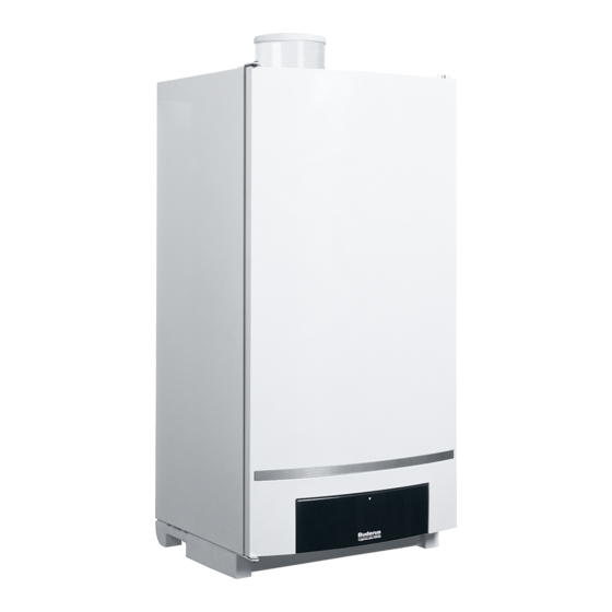
Page 2: Product Description
Product Description Product Description section 1 Product description Fig. 1 Logamax plus GB162 with pump group Logamax plus GB162-80 kW/100 kW - Subject to modifications resulting from technical improvements! -
Page 3: Product Description
Pressure gauge Isolating valve Thermometer (optional accessory) Drain valve Pressure relief valve 30 PSI (2 bar) (or 50 PSI [3.45 bar] = optional) Logamax plus GB162-80 kW/100 kW - Subject to modifications resulting from technical improvements! -
Page 4: Table Of Contents
Filling and bleeding the system ......58 Exploded view Logamax plus GB162-80 kW/100 kW ... 97 Switch on power supply . -
Page 5: General
Slight changes may be made without prior notice to the illustra- tions, process steps and technical data as a result of our policy of continuous improvement. Logamax plus GB162-80 kW/100 kW - Subject to modifications resulting from technical improvements! Cross-reference to Operating step with number... -
Page 6: Remedying Faults Using This Document
The right-hand column of the symptoms overview (section 5 "Symptoms" on page 21) refers to the corresponding diagnosis box. The diagnosis box can be used next to easily find the cause of the fault. Logamax plus GB162-80 kW/100 kW - Subject to modifications resulting from technical improvements! -
Page 7: Safety And General Instructions
Indicates special instructions on installation, opera- tion or maintenance that are important but not related to personal injury or property damage. Logamax plus GB162-80 kW/100 kW - Subject to modifications resulting from technical improvements! - Page 8 – The low loss header and boiler connection set must be installed (supplied with the boiler). – When using oxygen-permeable pipes (plastic), e.g. for floor heating systems, you must separate the system using sec- ondary heat exchangers. Logamax plus GB162-80 kW/100 kW - Subject to modifications resulting from technical improvements!
-
Page 9: Regulations And Guidelines
(30) day period, a battery operated car- ment at the completion of the installation. bon monoxide detector with an alarm shall be installed. Logamax plus GB162-80 kW/100 kW - Subject to modifications resulting from technical improvements! -
Page 10: Operation
The service mode should be used to carry out measurements and settings on the boiler. See also section 21, "Service Mode menu", page 14. Logamax plus GB162-80 kW/100 kW - Subject to modifications resulting from technical improvements! - Page 11 If there is a risk of radiators or pipe sections freezing up, we recommend setting the pump run-over time to 24 hours. See section 28 "Display settings". Logamax plus GB162-80 kW/100 kW - Subject to modifications resulting from technical improvements!
-
Page 12: Menu Structure
The LED "DHW demand" [11] lights up as soon as water is being heated as the result of a hot water demand and is extin- guished as soon as the heating system for DHW mode is switched off. Logamax plus GB162-80 kW/100 kW - Subject to modifications resulting from technical improvements! -
Page 13: Normal Operation Menu
Step 13 To deactivate the flue gas test: Step 1 Press and hold the " " button for more than 2 seconds until the dot disappears. Logamax plus GB162-80 kW/100 kW - Subject to modifications resulting from technical improvements! -
Page 14: Service Mode Menu
" button for more than 2 seconds until the dot disappears. → Step 25 The boiler performance is then reduced according to the settings made in the "Settings" menu in section 23, Step 1 page 15. Logamax plus GB162-80 kW/100 kW - Subject to modifications resulting from technical improvements! -
Page 15: Manual Operation Menu
Display setting: Target pump run-over time after heating mode has elapsed in minutes. [f/\/5| Set the second parameter as soon as the display shows [f/\/5| Recommendation: Do not set a pump run-over time of less than (= 5 minutes). Logamax plus GB162-80 kW/100 kW - Subject to modifications resulting from technical improvements! - Page 16 Display reading: Currently measured heating system supply temperature in °F. Step 1 See also section 27 "Display readings", page 21. Any adjustments that you have made have been confirmed. Logamax plus GB162-80 kW/100 kW - Subject to modifications resulting from technical improvements!
-
Page 17: Operation
Has the pump been out of use for more than 24 hours? Yes: Step 24 → Step 21 → Step 21 Is there a DHW heating system which has generated a demand? Yes: Step 29 → Step 22 Logamax plus GB162-80 kW/100 kW - Subject to modifications resulting from technical improvements! - Page 18 Start of air-side purging phase of the fan unit (section 1, [20]) for approx. 30 seconds. See also section 29 "Display codes and other symptoms", page 21. → Step 44 Have approx. 30 seconds elapsed? Yes: Step 45 → Step 44 Logamax plus GB162-80 kW/100 kW - Subject to modifications resulting from technical improvements!
- Page 19 Start of air-side flushing phase of the fan unit (section 1, [20]) for approx. 30 seconds. → Step 63 Have approx. 30 seconds elapsed? Yes: Step 64 → Step 63 → Step 64 The fan unit (section 1, [20]) stops. Step 15 Logamax plus GB162-80 kW/100 kW - Subject to modifications resulting from technical improvements!
- Page 20 The LED "Burner operation" is lit up. The boiler is in heating mode. → Step 70 Is the current heating-system supply temperature higher than 59 °F (15 °C)? Yes: Step 59 → Step 69 Logamax plus GB162-80 kW/100 kW - Subject to modifications resulting from technical improvements!
-
Page 21: Symptoms
On devices without DHW operation: no heating operation. → No display code No indication on the display of section 34 the BC10 (section 1, [4]). Logamax plus GB162-80 kW/100 kW - Subject to modifications resulting from technical improvements! - Page 22 [0/a/\| [3/0/5| Operating code:The heating boiler cannot start up temporarily after DHW mode has ended. Logamax plus GB162-80 kW/100 kW - Subject to modifications resulting from technical improvements!
- Page 23 (section 1, [28]) has measured a cur- possibly is not reached. 5) 7) rent supply temperature higher than 203 °F Possibly no DHW operation. (95 °C). Logamax plus GB162-80 kW/100 kW - Subject to modifications resulting from technical improvements!
- Page 24 The pump continues to run, but the pump speed is fixed. → [2/y/\| [2/8/2| Operating code: The tacho signal of the No heating operation and no section 44 pump is missing. DHW. Logamax plus GB162-80 kW/100 kW - Subject to modifications resulting from technical improvements!
- Page 25 Operating code: Component test phase using the Service Tool. [5/h/\| Blocking fault code: There is no communica- No heating operation. tion between RCC and UBA 3 (section 1, [32]). Logamax plus GB162-80 kW/100 kW - Subject to modifications resulting from technical improvements!
- Page 26 Locking fault code: The UBA 3 (section 1, flashing No heating operation and no section 66 [32]) or the KIM is defective. 1 Hz DHW. 4) 6) 7) 8) Logamax plus GB162-80 kW/100 kW - Subject to modifications resulting from technical improvements!
- Page 27 Blocking fault code: The supply temperature The mixer is not activated any- sensor of heating circuit address 2 indicates a more and stays in its last posi- fault. tion. Logamax plus GB162-80 kW/100 kW - Subject to modifications resulting from technical improvements!
- Page 28 DHW mode will be limited. → [p/-.-| Operating code: The water pressure of the section 65 heating system is beyond the measuring range of the pressure sensor (section 1, [30]). Logamax plus GB162-80 kW/100 kW - Subject to modifications resulting from technical improvements!
- Page 29 ) When this boiler fault occurs the pump is activated to run continuously, thus minimizing the risk of the heating system freezing up. [e/\/\| + random digit or letter. ) Only visible on certain RC room thermostats. ) Only visible on the Service Tool. Logamax plus GB162-80 kW/100 kW - Subject to modifications resulting from technical improvements!
-
Page 30: Diagnosis
Test the fuse on the rear of the UBA 3 using a multimeter, see section 82. → Step 24 Is the fuse working correctly? Yes: Section 66 → Step 25 Logamax plus GB162-80 kW/100 kW - Subject to modifications resulting from technical improvements! - Page 31 Diagnosis: The fan unit is defective. Action: Replace the fan unit, see section 86. Step 54 → Step 54 Replace the fuse again, see section 82. Section 67 Logamax plus GB162-80 kW/100 kW - Subject to modifications resulting from technical improvements!
- Page 32 Step 24 Check the DHW temperature sensor lead as indicated in section 94. → Step 25 Is the wire okay? Yes: Section 66 → Step 26 Logamax plus GB162-80 kW/100 kW - Subject to modifications resulting from technical improvements!
- Page 33 Action: Increase the setting of the RC regulator or ON/OFF controller as indicated in the Operating instructions for the regulator or controller. Step 4 Check that the LED "Central heat demand" on the BC10 lights up, see section 14. Logamax plus GB162-80 kW/100 kW - Subject to modifications resulting from technical improvements!
- Page 34 Step 29 → Step 30 → Step 29 Diagnosis: The servomotor of the three-way valve is defective. Action: Replace the servomotor of the three- Section 67 way valve. Logamax plus GB162-80 kW/100 kW - Subject to modifications resulting from technical improvements!
- Page 35 Has the thermostat cable been connected correctly? Yes: Step 8 → Step 7 → Step 7 Diagnosis: The thermostat cable has not been installed correctly. Section 67 Action: Connect the thermostat cable correctly. Logamax plus GB162-80 kW/100 kW - Subject to modifications resulting from technical improvements!
- Page 36 Action: Fix the dripping hot-water tap or the leakage in the hot-water pipe. Step 14 Find out whether a hot-water tap or taps have been opened on brief, consecutive occasions. Logamax plus GB162-80 kW/100 kW - Subject to modifications resulting from technical improvements!
- Page 37 Diagnosis: The heating system pressure is too low and is less than 14 PSI. Section 67 Action: Fill and bleed the heating system, see section 78. Step 5 Check that the boiler has been purged correctly, see section 78. Logamax plus GB162-80 kW/100 kW - Subject to modifications resulting from technical improvements!
- Page 38 Step 32 Diagnosis: There is no bypass, nor a low loss header. Section 67 Action: Install a bypass or a low loss header in the heating system. Logamax plus GB162-80 kW/100 kW - Subject to modifications resulting from technical improvements!
- Page 39 Diagnosis: The flue gas sensor is defective. Action: Replace the flue gas sensor, see section 99. Section 67 Step 4 Check the wiring of the flue gas sensor, see section 98. Logamax plus GB162-80 kW/100 kW - Subject to modifications resulting from technical improvements!
- Page 40 Is the pressure sensor dirty? Yes: Step 12 → Step 13 → Step 12 Diagnosis: The pressure sensor is dirty. Action: Clean the pressure sensor, see section 128. Section 67 Logamax plus GB162-80 kW/100 kW - Subject to modifications resulting from technical improvements!
- Page 41 Attempt to rectify the fault by temporarily replacing the pump, see section 92. → Step 19 Has the fault been remedied? Yes: Section 67 → Section 66 Logamax plus GB162-80 kW/100 kW - Subject to modifications resulting from technical improvements!
- Page 42 Diagnosis: The fan unit is defective. Action: Replace the fan unit, see section 86. → Step 16 Has the fault been remedied? Yes: Section 67 → Section 66 Logamax plus GB162-80 kW/100 kW - Subject to modifications resulting from technical improvements!
- Page 43 Check that the main voltage at the grounded plug is between 102 VAC and 132 VAC. → Step 8 Is the main voltage okay? Yes: Step 10 → Step 9 Logamax plus GB162-80 kW/100 kW - Subject to modifications resulting from technical improvements!
- Page 44 Are the service valves open as instructed in section 78? Yes: Step 3 → Step 2 Step 2 Diagnosis: The service valves are closed. Action: Open the service valves, see section 78. Logamax plus GB162-80 kW/100 kW - Subject to modifications resulting from technical improvements!
- Page 45 Are the wires okay? Yes: Section 66 → Step 6 → Step 6 Diagnosis: The wire harness is defective. Action: Replace the wire harness or the affected part. Section 67 Logamax plus GB162-80 kW/100 kW - Subject to modifications resulting from technical improvements!
- Page 46 Is the electrical resistance of the glow ignitor okay? Yes: Step 26 → Step 25 → Step 25 Diagnosis: The glow ignitor is defective. Action: Replace the glow ignitor, see section 103. Section 67 Logamax plus GB162-80 kW/100 kW - Subject to modifications resulting from technical improvements!
- Page 47 Step 49 → Step 48 → Step 48 Diagnosis: The wrong orifice has been installed. Section 67 Action: Fit the correct orifice, see section 113 and 135. Logamax plus GB162-80 kW/100 kW - Subject to modifications resulting from technical improvements!
- Page 48 Is the ionization electrode okay? Yes: Section 66 → Step 3 → Step 3 Diagnosis: The ionization electrode is defective. Action: Replace the ionization electrode, see section 103. Section 67 Logamax plus GB162-80 kW/100 kW - Subject to modifications resulting from technical improvements!
- Page 49 Check that there is no obstruction in other parts of the gas pipe. → Step 14 Did you find an obstruction? Yes: Step 15 → Step 24 Logamax plus GB162-80 kW/100 kW - Subject to modifications resulting from technical improvements!
- Page 50 Diagnosis: The above components are dirty, damaged or not correctly installed. Section 67 Action: Clean, replace and/or re-install the relevant components. Step 37 Check the ionization current as indicated in section 104. Logamax plus GB162-80 kW/100 kW - Subject to modifications resulting from technical improvements!
- Page 51 Has the fault been remedied? Yes: Section 67 → Step 3 Step 3 Diagnosis: The KIM is defective. Action: Contact the manufacturer. See the back of this document for contact details. Logamax plus GB162-80 kW/100 kW - Subject to modifications resulting from technical improvements!
- Page 52 Diagnosis: The external switch contact has opened or a wire has broken in the external switch contact Section 67 wiring outside the boiler. Action: Remedy the cause of the external switch contact opening or replace the wiring. Logamax plus GB162-80 kW/100 kW - Subject to modifications resulting from technical improvements!
- Page 53 Step 9 Check that the three-way valve has been installed correctly. → Step 10 Has the three-way valve been installed correctly? Yes: Step 18 → Step 11 Logamax plus GB162-80 kW/100 kW - Subject to modifications resulting from technical improvements!
- Page 54 Diagnosis: The pressure sensor is defective. Action: Replace the pressure sensor, see section 128. → Step 11 Has the fault been remedied? Yes: Section 67 → Section 66 Logamax plus GB162-80 kW/100 kW - Subject to modifications resulting from technical improvements!
- Page 55 Put the main power switch on the control panel in position "1" (On), see section 80. The fault has now been rectified! The Logamax plus GB162-80 kW/100 kW is working correctly! Logamax plus GB162-80 kW/100 kW - Subject to modifications resulting from technical improvements!
-
Page 56: Actions
[1]. After completing the service activites, install the BC10 on the boiler door in reverse order of removal and secure the BC10 with the 2 screws. Logamax plus GB162-80 kW/100 kW - Subject to modifications resulting from technical improvements! -
Page 57: Closing Cover Of The Bc10
Push the lock down [2] and open the door [3]. boiler. If a pump group is available: Remove the casing of the pump group [4]. Logamax plus GB162-80 kW/100 kW - Subject to modifications resulting from technical improvements! -
Page 58: Opening Isolating Valves
Purge the heating system via the air vents on the heating clockwise using a bleed key [3]. bodies. Start at the lowest floor of the premises and then work your way up from floor to floor. Logamax plus GB162-80 kW/100 kW - Subject to modifications resulting from technical improvements! -
Page 59: Switch On Power Supply
If the water pres- sure is less than 14 PSI, the heating system has to be topped up again as described above. Logamax plus GB162-80 kW/100 kW - Subject to modifications resulting from technical improvements! -
Page 60: Initial Startup
Close main gas shut off valve. 708.375A - 2172B Open the boiler door and remove the casing of the pump group as instructed in section 73. Logamax plus GB162-80 kW/100 kW - Subject to modifications resulting from technical improvements! -
Page 61: Checking/Replacing Fuses
Switch on the power supply to the heating system, see Close the boiler door as instructed in section 77. section 79. Switch on the power supply to the heating system, see, section 79. Logamax plus GB162-80 kW/100 kW - Subject to modifications resulting from technical improvements! -
Page 62: Checking The Fan Unit; Power Supply Cord (120 Vac)
Close the boiler door as instructed in section 77. Switch on the power supply to the heating system, see Switch on the power supply to the heating system, see section 79. section 79. Logamax plus GB162-80 kW/100 kW - Subject to modifications resulting from technical improvements! -
Page 63: Checking And/Or Replacing The Fan Unit
Remove both the fan unit power supply cord plug [1] and the fan unit tacho cable plug [2]. Logamax plus GB162-80 kW/100 kW - Subject to modifications resulting from technical improvements! -
Page 64: Checking The Pump; Mechanical Obstruction
Install the casing of the pump group as indicated in Install the new fan unit in reverse order on the burner cover. section 77. Close the cover of the BC10 in reverse order. Logamax plus GB162-80 kW/100 kW - Subject to modifications resulting from technical improvements! -
Page 65: Checking The Pump; Activation
250 VAC [1]. Attach the pump power supply cord plug in reverse order of Switch on the power supply to the heating system, see removal. section 79. Logamax plus GB162-80 kW/100 kW - Subject to modifications resulting from technical improvements! -
Page 66: Checking The Pump; Tacho Cable
Attach the pump tacho cable plug in reverse order of removal. Install the lid on the connection tray in reverse order. Install the UBA 3 in reverse order of removal. Logamax plus GB162-80 kW/100 kW - Subject to modifications resulting from technical improvements! -
Page 67: Checking The Pump; Pollution
/ or the center of the pump impeller wheel. Install the upper part of the pump in reverse order. Fill and purge the heating system, see section 78. Logamax plus GB162-80 kW/100 kW - Subject to modifications resulting from technical improvements! -
Page 68: Checking The Supply, Safety, Return And Dhw Temperature Sensors
Measure the electrical resistance of the return temperature sensor [3]. Measure the electrical resistance over the return temperature sensor to ground. This electrical resistance must be infinite. Logamax plus GB162-80 kW/100 kW - Subject to modifications resulting from technical improvements! -
Page 69: Checking The Supply, Safety, Return And Dhw Temperature Sensors; Cables
The electrical resistance must be infinite for every individual wire. Disconnect the safety temperature sensor plug as instructed in section 93, [1]. Logamax plus GB162-80 kW/100 kW - Subject to modifications resulting from technical improvements! - Page 70 Disconnect the return temperature sensor plug as instructed in section 93, [1]. Disconnect the DHW temperature sensor (FW) plug in the connection tray [1]. Logamax plus GB162-80 kW/100 kW - Subject to modifications resulting from technical improvements!
-
Page 71: Replacing The Feed, Safety And Return Sensors
0 [2]. Measure between the connection tray and the black contacts (low-voltage connector pins 63 and 64) on the UBA 3 mounting base [3]. Logamax plus GB162-80 kW/100 kW - Subject to modifications resulting from technical improvements! -
Page 72: Replacing The Dhw Temperature Sensor
78. Disconnect the plug of the flue gas sensor [1]. Switch on the power supply to the heating system, see section 79. Logamax plus GB162-80 kW/100 kW - Subject to modifications resulting from technical improvements! -
Page 73: Checking The Flue Gas Sensor; Cable
Install the UBA 3 in reverse order of removal. Close the boiler door as instructed in section 73. Switch on the power supply to the heating system, see section 79. Logamax plus GB162-80 kW/100 kW - Subject to modifications resulting from technical improvements! -
Page 74: Replacing The Flue Gas Sensor
Attach the plug of the glow ignitor in reverse order. Close the boiler door in reverse order. Switch on the power supply to the heating system, see section 79. Logamax plus GB162-80 kW/100 kW - Subject to modifications resulting from technical improvements! -
Page 75: Checking The Glow Ignitor; Resistance
Install the UBA 3 in reverse order of removal. Close the boiler door as instructed in section 77. Switch on the power supply to the heating system, see section 79. Logamax plus GB162-80 kW/100 kW - Subject to modifications resulting from technical improvements! -
Page 76: Replacing The Ignition Unit
DANGER OF FATAL ACCIDENT/FIRE due to flue gas escaping or explosion of flamable gases. All work on gas pipe work and fittings must be carried out by authorized gas technicians. Logamax plus GB162-80 kW/100 kW - Subject to modifications resulting from technical improvements! -
Page 77: Checking The Ionization Electrode; Short Circuit
Attach the plug of the ionization electrode in reverse order. Close the boiler door as instructed in section 77. Switch on the power supply to the heating system, see section 79. Logamax plus GB162-80 kW/100 kW - Subject to modifications resulting from technical improvements! -
Page 78: Checking The Ionization Electrode; Cable
Carry out a measurement to make sure that there is no break- age in the ionization electrode. The electrical resistance of Ω the ionization electrode cable must be approximately 0 [2]. Logamax plus GB162-80 kW/100 kW - Subject to modifications resulting from technical improvements! -
Page 79: Checking The Ionization Circuit; Ground Lead
Switch on the power supply to the heating system, see Stop the flue gas test as instructed in section 20. section 79. Close the boiler door as instructed in section 77. Logamax plus GB162-80 kW/100 kW - Subject to modifications resulting from technical improvements! -
Page 80: Checking The Gas Valve; Electrical Resistance Of The Power Supply Cord
Close the boiler door as instructed in section 77. Switch on the power supply to the heating system, see Switch on the power supply to the heating system, see section 79. section 79. Logamax plus GB162-80 kW/100 kW - Subject to modifications resulting from technical improvements! -
Page 81: Replacing The Gas Valve
Check the gas/air ratio and adjust it if necesaary, see section 119. Install a new O-ring [1] in the venturi pipe. Close the boiler door as instructed in section 91. Logamax plus GB162-80 kW/100 kW - Subject to modifications resulting from technical improvements! -
Page 82: Checking The On/Off Controller
Switch on the power supply to the heating system, see section 79. Adjust the selector for the DHW temperature setting on the control panel to the required position, as instructed in section 81, [1]. Logamax plus GB162-80 kW/100 kW - Subject to modifications resulting from technical improvements! -
Page 83: Checking An External Switch Contact
Check the gas connection pressure testing nipple for leaks using a foaming agent which has been approved for gas leak testing. Zero the digital pressure gauge. Logamax plus GB162-80 kW/100 kW - Subject to modifications resulting from technical improvements! -
Page 84: Bleeding The Gas Supply Pipe
Briefly wait for the boiler to modulate down to minimum testing. capacity. Close the boiler door as instructed in section 77. Switch on the power supply to the heating system, see section 79. Logamax plus GB162-80 kW/100 kW - Subject to modifications resulting from technical improvements! -
Page 85: Checking The Transformer; Internal Electrical Resistance
Put the boiler in flue gas test mode as indicated in section 20. Close the boiler door as instructed in section 77. Logamax plus GB162-80 kW/100 kW - Subject to modifications resulting from technical improvements! -
Page 86: Checking The Transformer; Power Supply Cord And Low-Voltage Cord
Measure the electrical resistance over the power supply cord and the low-voltage cord to ground. The electrical resistance must be infinite for every individual wire. Install the transformer in reverse order. Logamax plus GB162-80 kW/100 kW - Subject to modifications resulting from technical improvements! -
Page 87: Checking The Wire Harness; Connections
Install the UBA 3 in reverse order of removal. Close the boiler door as instructed in section 77. Switch on the power supply to the heating system, see section 79. Logamax plus GB162-80 kW/100 kW - Subject to modifications resulting from technical improvements! -
Page 88: Replacing The Automatic Air Purging System
Close the boiler door as instructed in section 77. Switch on the power supply to the heating system, see section 79. Open the gas stop valve as indicated in section 81. Logamax plus GB162-80 kW/100 kW - Subject to modifications resulting from technical improvements! -
Page 89: Replacing/Cleaning The Siphon
Install the casing of the pump group in reverse order of the various parts and components. removal. Switch on the power supply to the heating system, see section 79. Logamax plus GB162-80 kW/100 kW - Subject to modifications resulting from technical improvements! - Page 90 Remove both clamp springs. Remove both the ground lead of the heat exchanger and the ground lead of the ionization circuit as instructed in section 108. Logamax plus GB162-80 kW/100 kW - Subject to modifications resulting from technical improvements!
-
Page 91: Replacing The Uba 3
Close the boiler door and install the casing of the pump group in reverse order of removal. Switch on the power supply to the heating system, see section 79. Logamax plus GB162-80 kW/100 kW - Subject to modifications resulting from technical improvements! -
Page 92: Appendix
29 30 18 19 20 21 22 Logamax plus GB162-80 kW/100 kW - Subject to modifications resulting from technical improvements! -
Page 93: Legend Of Electrical Wiring Diagram
5 A 18,787 1,255 28: Mains switch 15,136 1,084 29: 120 VAC function module 12,268 30: Ground 10,000 8,197 6,754 5,594 4,656 3,893 3,271 2,760 2,339 1,990 1,700 Logamax plus GB162-80 kW/100 kW - Subject to modifications resulting from technical improvements! -
Page 94: Technical Specifications Of Gb162-Boilers At Sea Level (0-4,000 Ft)
Ø flue gas system, room-air dependent in (mm) Ø 4” (100 mm) Ø flue gas system, room-air independent in (mm) Ø 4” (100 mm) / 4” (100 mm) parallel Logamax plus GB162-80 kW/100 kW - Subject to modifications resulting from technical improvements! - Page 95 (m) mm (inch) Natural gas 0 - 4,000 (0 - 1,220) 8.40 (0.331) 7746900399 GB162-80 KW/100 KW 0 - 4,000 (0 - 1,220) 4.70 (0.185) 7746900499 Logamax plus GB162-80 kW/100 kW - Subject to modifications resulting from technical improvements!
-
Page 96: Spare Parts List
BCM 1100 – 100 kW (0-4,000 ft) 7746900394 – BCM 1101 – 80 kW (0-4,000 ft) 7746900395 Heat exchanger 7746900383 – Screw 6.3 x 19 (10 pc) 73986 Logamax plus GB162-80 kW/100 kW - Subject to modifications resulting from technical improvements! -
Page 97: Exploded View Logamax Plus Gb162-80 Kw/100 Kw
Appendix section 138 Exploded view Logamax plus GB162-80 kW/100 kW 44 45 Logamax plus GB162-80 kW/100 kW - Subject to modifications resulting from technical improvements! -
Page 98: Exploded View Pump Group Logamax Plus Gb162-80 Kw/100 Kw
Appendix section 139 Exploded view pump group Logamax plus GB162-80 kW/100 kW Logamax plus GB162-80 kW/100 kW - Subject to modifications resulting from technical improvements! - Page 99 Draining the system ......57 Electrical wiring diagram ..... .92 Logamax plus GB162-80 kW/100 kW - Subject to modifications resulting from technical improvements!
Need help?
Do you have a question about the Logamax plus GB162-80 kW and is the answer not in the manual?
Questions and answers