Table of Contents
Advertisement
Installation instructions
Logamax plus
GB162-L.B. 80 kW
GB162-L.B. 100 kW
Read carefully before carrying out installation and maintenance.
CAUTION!
Before putting the boiler into operation read this manual carefully.
DANGER!
Improper installation, adjustment, alteration, service or maintenance can
cause injury, loss of life or property damage. Refer to this manual.
For assistance or additional information consult a qualified installer,
service agency or the gas supplier.
CAUTION!
The operating manual is part of the documentation that is delivered to the
installation's operator. Go through the information in this manual with the
owner/operator and make sure that he or she is familiar with all the
necessary operating instructions.
NOTICE!
In the Commonwealth of Massachusetts this boiler must be installed by a
licensed Plumber or Gas Fitter.
Danger: If the information in these instructions is not followed
exactly, a fire or explosion may result causing property damage,
personal injury or loss of life.
• Do not store or use gasoline or other flammable vapors and liquids
in the vicinity of this or any other appliance.
• What to do if you smell gas
– Do not try to light any boiler.
– Do not touch any electrical switch; do not use any phone in your
building.
– Immediately call your gas supplier from a neighbor's phone.
Follow the gas supplier's instructions.
– If you cannot reach your gas supplier, call the fire department.
• Installation and service must be performed by a qualified installer,
service agency or the gas supplier.
6720645916-00.1N
Notice!
• This manual is available in the English and French language.
• This manual must be retained for future reference.
Condensing gas boiler
Advertisement
Table of Contents

Related Manuals for Buderus Logamax plus GB162-L.B. 80 kW


Summary of Contents for Buderus Logamax plus GB162-L.B. 80 kW
- Page 1 Condensing gas boiler CAUTION! Before putting the boiler into operation read this manual carefully. DANGER! Improper installation, adjustment, alteration, service or maintenance can cause injury, loss of life or property damage. Refer to this manual. For assistance or additional information consult a qualified installer, service agency or the gas supplier.
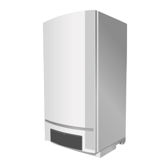
- Page 2 6720645916-01.TD Fig. 1 Logamax plus GB162-L.B. with pump group Logamax plus GB162-L.B. 80 kW / 100 kW – 6720645916 (2014/10)
- Page 3 [44] Safety valve 30 psi (2 bar) (or 50 psi [3.45 bar] = optional) The pump group also includes an insulation cover (see also pump group installation instructions). Low loss header (single appliance only): [45] Low loss header (not illustrated) Logamax plus GB162-L.B. 80 kW / 100 kW – 6720645916 (2014/10)
-
Page 4: Table Of Contents
Remove the boiler door ......43 Installing function modules (accessories) ..26 Logamax plus GB162-L.B. 80 kW / 100 kW – 6720645916 (2014/10) -
Page 5: Explanation Of Symbols And Safety Information
▶ Beware if you smell gas: there may be an explosion hazard! ▶ Do not store or use gasoline or other flammable vapors and liquids in the vicinity of this or any other boiler. Logamax plus GB162-L.B. 80 kW / 100 kW – 6720645916 (2014/10) -
Page 6: Regulations And Guidelines
• The boiler must not be installed on carpeting. period, a battery operated carbon monoxide detector with an alarm shall be installed. alarm and battery back-up may be installed on the next adjacent floor level. Logamax plus GB162-L.B. 80 kW / 100 kW – 6720645916 (2014/10) -
Page 7: General Information
For all Product Approved side wall horizontally vented gas fueled equipment, all venting instructions, all parts lists for venting instructions, and/or venting design instructions shall remain with the appliance or equipment at the completion of the installation. Logamax plus GB162-L.B. 80 kW / 100 kW – 6720645916 (2014/10) -
Page 8: Heating System Water Quality
▶ Dispose of the boiler packaging in an environmentally sound manner. ▶ Dispose of components of the heating system (e. g. boiler or control device), that must be replaced in an environmentally responsible manner. Logamax plus GB162-L.B. 80 kW / 100 kW – 6720645916 (2014/10) -
Page 9: Dimensions And Connections
16.5" + 20.5" = 37" (940 mm). Maintain an installation clearance from combustible construction from hot water piping of at least 1" (25 mm). Logamax plus GB162-L.B. 80 kW / 100 kW – 6720645916 (2014/10) -
Page 10: With Pump Group
= Gas connection to pump group; 1" NPT female thread hot water piping of at least 1" (25 mm). (PR) = Pump group return; G1½" male thread, flat seal Logamax plus GB162-L.B. 80 kW / 100 kW – 6720645916 (2014/10) -
Page 11: Packaging And Transportation
Table 3 Items supplied with GB162-L.B. 80 kW/100 kW Additional required accessories (not in delivery content) A single boiler must be installed with the Buderus low loss header (LLH) to regulate the flow. The low loss header must be ordered separately. -
Page 12: Installation
▶ Never use salt bedding type exchangers (ion exchangers) to soften the water. ▶ The low loss header and boiler connection set must be installed (supplied with the boiler). Logamax plus GB162-L.B. 80 kW / 100 kW – 6720645916 (2014/10) -
Page 13: Water And Gas Connection
The water and gas connections to the boiler are made using the pump group ( fig. 4, page 11). This pump group includes the circulation pump and a pressure relief valve. 6 720 646157-11.1TD Fig. 12 Low loss header Logamax plus GB162-L.B. 80 kW / 100 kW – 6720645916 (2014/10) -
Page 14: Connecting The Pressure Relief Valve (Prv)
/hr, based on a specific gravity of 60 (42 mbar) and a inlet gas pressure of 14" W.C. (35 mbar) or less and a pressure drop of 3" W.C. (20 mbar) Logamax plus GB162-L.B. 80 kW / 100 kW – 6720645916 (2014/10) -
Page 15: Installing The Pump
1½" (38 mm). 6.4.5 Installing the pump Always use the supplied Buderus pump group and the low loss header when installing a single boiler so correct flows are guaranteed. It is not necessary to install a low loss header for cascade systems. -
Page 16: Connecting The Condensate Drain Pipe
– The condensate produced by the boiler has a pH value between ▶ Avoid excessive dust formation and build-up. 3 and 4. ▶ Install a neutralization unit if required by the local code. Logamax plus GB162-L.B. 80 kW / 100 kW – 6720645916 (2014/10) -
Page 17: Flue Gas Adapter
(crawl or attic) that freely communicate with the outdoors. The minimum dimension of air openings shall be no less than 4" (101.6 mm). 7 746 800 103-09.1D Fig. 21 Placing air intake cap Logamax plus GB162-L.B. 80 kW / 100 kW – 6720645916 (2014/10) -
Page 18: Installation Of The Exhaust And Air Intake System
INTAKE 12" (305 mm) minimum 12" (305 mm) 12" (305 mm) minimum minimum 6 720 646916-21.1N Fig. 23 Vent and air pipe position (1) of a sealed combustion system Logamax plus GB162-L.B. 80 kW / 100 kW – 6720645916 (2014/10) - Page 19 Height at Least 1ft (305 mm) above grade and snow line Exhaust terminal must be at least 3 ft. (915 mm) above forced air inlet within 10 ft. (3,050 mm) Forced Air Inlet Gravity Air Inlet Logamax plus GB162-L.B. 80 kW / 100 kW – 6720645916 (2014/10)
- Page 20 Fig. 25 Horizontal venting system (sealed combustion) exhaust 4" (100 mm) intake 4" (100 mm) 6 720 645 916-29.2TD Fig. 27 Horizontal venting system (sealed combustion) exhaust 4" (100 mm) intake 4" (100 mm) Logamax plus GB162-L.B. 80 kW / 100 kW – 6720645916 (2014/10)
- Page 21 4" (100 mm) combustion) intake 4" (100 mm) 12" (300 mm) over maximum snow level or 24" (600 mm) exhaust 4" (100 mm) whichever is greater intake 4" (100 mm) Logamax plus GB162-L.B. 80 kW / 100 kW – 6720645916 (2014/10)
- Page 22 PolyPro Wall terminal 4"/6" (100/150 mm) 20.3 concentric PolyPro Roof terminal 4"/6" (100/150 mm) 26.0 PolyPro Roof terminal Flex Chimney Cap Table 8 Friction Loss Equivalent in piping and fittings Logamax plus GB162-L.B. 80 kW / 100 kW – 6720645916 (2014/10)
-
Page 23: Multiple Boiler Vent Terminal Clearance
The combustion air inlet is part of the direct vent system and not classified as a forced air inlet. Logamax plus GB162-L.B. 80 kW / 100 kW – 6720645916 (2014/10) -
Page 24: Electrical Connections
▶ Route and attach the cable for the 120 VAC connections using the strain relief clamps [3]. ▶ Only the 120 V electrical connections require a 14 gauge wire. Logamax plus GB162-L.B. 80 kW / 100 kW – 6720645916 (2014/10) -
Page 25: Low Voltage Connections
Buderus pump group) grey DHW tank pump 120 VAC lilac DHW recirculation pump 120 VAC Netz white Main power connection 120 VAC Table 9 External connection board connections Logamax plus GB162-L.B. 80 kW / 100 kW – 6720645916 (2014/10) -
Page 26: Controller
▶ Connect the external heating or system pump (for situations where Installing function modules (accessories) the pump of the Buderus pump group is not used) to the green PK terminal ( fig. 38). The maximum allowed connected load of the NOTICE pump = 100 Watts. - Page 27 ▶ Connect the wire from terminal 1 to terminal 1 and from terminal 2 to terminal 2 ( fig. 44 and fig. 45). 6 720 646157-40.1N Fig. 43 Removing the covers Logamax plus GB162-L.B. 80 kW / 100 kW – 6720645916 (2014/10)
-
Page 28: Installing Function Modules Outside The Boiler
[1]. 6 720 646157-44.1N Fig. 47 External connection board - Room controller RC and EMS bus (connection color orange) ▶ To connect other modules, see § 7.2.1. 6720645916 (2014/10) Logamax plus GB162-L.B. 80 kW / 100 kW... -
Page 29: Electrical Wiring Diagram
Connection for pump in connection kit (accessory) For location of individual components, see service section and the exploded Gas valve views in this manual. Transformer Glow ignitor Earth Logamax plus GB162-L.B. 80 kW / 100 kW – 6720645916 (2014/10) -
Page 30: Operation
This is only required in the event of a “locking” fault. “Blocking” faults are extinguished when the DHW demand is no longer present. reset automatically as soon as their cause has been corrected. The display shows [\/r/e| during the reset operation. Logamax plus GB162-L.B. 80 kW / 100 kW – 6720645916 (2014/10) -
Page 31: Bc10 Operating Instructions
[f/\/5] This parameter shows the pump run-over time in minutes that starts when the heating mode has ended ( § 13.4, page 48). Step 8 Table 13 Service mode Logamax plus GB162-L.B. 80 kW / 100 kW – 6720645916 (2014/10) - Page 32 After 5 seconds or after a power interruption the settings menu ends automatically. To end manually press the e button. Step 9 Any adjustments that you have made have been confirmed. Table 15 Settings Logamax plus GB162-L.B. 80 kW / 100 kW – 6720645916 (2014/10)
-
Page 33: Start-Up Procedure
Turn off all electric power to the appliance if service is to be performed. Set the thermostat or other operating control to lowest setting. Close main gas shut off valve. 708.375A - 2172B 6720645916-48.1N Fig. 51 Safety sticker Logamax plus GB162-L.B. 80 kW / 100 kW – 6720645916 (2014/10) -
Page 34: Check For Gas Leaks
To purge the boiler, every radiator in the heating system must have a purge facility. In some situations it may even be necessary to provide extra purging facilities at certain locations. The boiler itself has an automatic air vent. Logamax plus GB162-L.B. 80 kW / 100 kW – 6720645916 (2014/10) -
Page 35: Fill The Condensate Trap With Water
▶ Read the pressure (PSI) from the pressure gauge on the pump group or on the control panel of the BC10 ( fig. 57). 20 30 6720645916-56.1N Fig. 59 Closing the gas valve 6720645916-54.1N Fig. 57 Reading the pressure gauge Logamax plus GB162-L.B. 80 kW / 100 kW – 6720645916 (2014/10) -
Page 36: Check The Air/Flue Gas Connection
• Is the prescribed flue gas system used ( § 6.8, page 18)? • Have the configuration instructions from the relevant flue gas system installation instructions been observed? 6720645916-60.1N Fig. 63 Closing the gas valve Logamax plus GB162-L.B. 80 kW / 100 kW – 6720645916 (2014/10) - Page 37 Table 17 Gas supply pressure 1) Measured statically perpendicular to flow at full load. ▶ Press the “Service” button ( fig. 65, [4]) repeatedly until the temperature reading is shown in the display. Logamax plus GB162-L.B. 80 kW / 100 kW – 6720645916 (2014/10)
-
Page 38: Carry Out A Leakage Test In Operating Conditions
▶ Switch ON the appliance by pressing the main switch of the BC10 ▶ Open the screw plug. basic controller. ▶ Turn adjustment screw to the left for a lower CO percentage. Logamax plus GB162-L.B. 80 kW / 100 kW – 6720645916 (2014/10) -
Page 39: Function Test
▶ Turn the vent key through a quarter turn to undo the boiler door lock ▶ Enter the result in the start-up report ( § 15.1, page 56). ( fig. 54, step 1). Logamax plus GB162-L.B. 80 kW / 100 kW – 6720645916 (2014/10) -
Page 40: Test The Ignition Safety Shut Off Device
“space heating water temperature” knob ( fig. 72, temperature is 140 °F (60 °C). [8]) ( table 19). This limitation does not apply to DHW Table 20 Setting of the “DHW temperature” preparation. Logamax plus GB162-L.B. 80 kW / 100 kW – 6720645916 (2014/10) -
Page 41: Final Activities
8 "Operation", page 30. ▶ Push on the control panel to open it. ▶ Switch OFF the appliance by pressing the main switch of the BC10 ( fig. 72, [1]). Logamax plus GB162-L.B. 80 kW / 100 kW – 6720645916 (2014/10) -
Page 42: Inspection
8.0" W.C. (19.9 mbar) for LPG. ▶ Check that the appliance is switched OFF. ▶ Open the screw plug on the testing nipple for the gas connection by 2 turns ( fig. 78, [1]). Logamax plus GB162-L.B. 80 kW / 100 kW – 6720645916 (2014/10) -
Page 43: Measure The Ionization Current
▶ Slightly lift the door and pull it from the hinge. ▶ Put the door upright in a safe position. NOTICE ▶ The cover over the electrical connections does not have to be removed from the boiler. Logamax plus GB162-L.B. 80 kW / 100 kW – 6720645916 (2014/10) -
Page 44: Clean The Heat Exchanger, Burner And Condensate Trap
( fig. 84). The retaining clips may be under tension. ▶ Remove the retaining clips. 6720645916-80.1N Fig. 81 Undoing the connections to the gas fitting 6720645916-83.1N Fig. 84 Opening the retaining clips Logamax plus GB162-L.B. 80 kW / 100 kW – 6720645916 (2014/10) -
Page 45: Remove The Burner And The Burner Seal
6720615405-035.1TD Fig. 88 Replacing the ignition unit NOTICE The glow ignitor is fragile. glow ignitor ▶ Handle with care. Ionization electrode Rubber seal Cover plate with seal Logamax plus GB162-L.B. 80 kW / 100 kW – 6720645916 (2014/10) -
Page 46: Disconnect The Condensate Trap
▶ Fill the condensate trap with water and reinstall it. NOTICE ▶ The condensate trap has a bayonet connector. After inserting it, the condensate trap must be turned ¼ rotation clockwise to click into position. Logamax plus GB162-L.B. 80 kW / 100 kW – 6720645916 (2014/10) -
Page 47: Clean The Heat Exchanger
▶ Flue gas or condensate may leak ▶ Clean the heat exchanger with compressed air or a soft brush ( fig. 94). 6720645916-47.1N Fig. 95 BC10 basic controller 6720645916-93.1N Fig. 94 Cleaning the heat exchanger Logamax plus GB162-L.B. 80 kW / 100 kW – 6720645916 (2014/10) -
Page 48: Display Information
DHW flow operating condition setting. NOTE: If the setting [c/\/0| is displayed, the frost protection of the DHW flow has also been switched off. Table 22 BC10 Display settings Logamax plus GB162-L.B. 80 kW / 100 kW – 6720645916 (2014/10) -
Page 49: Bc10 Display Codes
DHW mode. Table 23 Display codes Logamax plus GB162-L.B. 80 kW / 100 kW – 6720645916 (2014/10) - Page 50 [4/a/\| [2/1/8| Blocking fault: No heating operation and no DHW. The flow temperature sensor has detected a flow temperature of over 221 °F (105 °C) Table 23 Display codes Logamax plus GB162-L.B. 80 kW / 100 kW – 6720645916 (2014/10)
- Page 51 The boiler starts up after activation of the mains power supply or completion of a system reset. This code is displayed for a maximum of 4 minutes. Table 23 Display codes Logamax plus GB162-L.B. 80 kW / 100 kW – 6720645916 (2014/10)
- Page 52 1 and DHW. Depending on the heating programs set and the required room temperatures, the heating system can no longer work correctly. DHW mode does not work well. Table 23 Display codes Logamax plus GB162-L.B. 80 kW / 100 kW – 6720645916 (2014/10)
- Page 53 1) Any display code with a dot in bottom right hand corner. 2) Any display code with a blinking dot in bottom right hand corner. 3) Any display code starting with the letter E (except EL). Logamax plus GB162-L.B. 80 kW / 100 kW – 6720645916 (2014/10)
-
Page 54: Technical Specifications
Ø Flue gas system, room-air dependent in (mm) Ø 4" (100) Ø Flue gas system, room-air independent in (mm) Ø 4" (100)/ 4" (100) parallel Table 24 Technical specifications of GB162-boilers at low BTU Logamax plus GB162-L.B. 80 kW / 100 kW – 6720645916 (2014/10) - Page 55 2.90 2.18 1.45 0.73 1000 1500 2000 2500 3000 3500 4000 4500 5000 11.0 13.2 15.4 17.6 19.8 22.0 6720645916-98.1N Fig. 99 Boiler resistance curve Volume flow Pressure drop Logamax plus GB162-L.B. 80 kW / 100 kW – 6720645916 (2014/10)
-
Page 56: Reports
13. Boiler settings page 40 14. Final activities page 41 Close the boiler door and the control panel Hand over Confirming proper start-up Company stamp/signature/date Table 27 Start-up report Logamax plus GB162-L.B. 80 kW / 100 kW – 6720645916 (2014/10) -
Page 57: Inspection Report
47 Confirming proper inspection Company Company Company Company Company Company Company stamp/ stamp/ stamp/ stamp/ stamp/ stamp/ stamp/ signature signature signature signature signature signature signature Table 29 Service report Logamax plus GB162-L.B. 80 kW / 100 kW – 6720645916 (2014/10) -
Page 58: Spare Parts
Clip (4 x 2 pc) 7746700063 105 Valve housing return 74549 O-ring 9.19 x 2.62 (10 pc) 78175s 106 Air release tap 7746900403 Table 30 Spare parts Table 30 Spare parts Logamax plus GB162-L.B. 80 kW / 100 kW – 6720645916 (2014/10) - Page 59 AM10 7746900020 HCM 1231 – 100 kW (4,001-10,200 ft.) 8718600324 HCM 1232 – 80 kW (4,001-10,200 ft.) 8718600325 Screw 6.3 x 19 (10 pc) 73986 Table 30 Spare parts Logamax plus GB162-L.B. 80 kW / 100 kW – 6720645916 (2014/10)
- Page 60 Spare parts 44 45 46 47 6720645916-99.2TD Fig. 100 Exploded view Logamax plus GB162-L.B. 80 kW/100 kW Logamax plus GB162-L.B. 80 kW / 100 kW – 6720645916 (2014/10)
- Page 61 Spare parts 6720645916-100.2TD Fig. 101 Exploded view pump group GB162-L.B. 80 kW/100 kW Logamax plus GB162-L.B. 80 kW / 100 kW – 6720645916 (2014/10)
-
Page 62: Index
Gas tightness ............Gas/air ratio ..........Heat exchanger ............ Heating capacity ..........Heating system water ..........Hydraulic resistance ............Ignition unit ........... Inspection report ............ Installation room ........... Ionization current Logamax plus GB162-L.B. 80 kW / 100 kW – 6720645916 (2014/10) - Page 63 Notes Logamax plus GB162-L.B. 80 kW / 100 kW – 6720645916 (2014/10)
Need help?
Do you have a question about the Logamax plus GB162-L.B. 80 kW and is the answer not in the manual?
Questions and answers