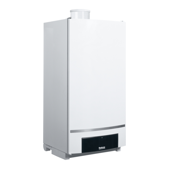
Buderus Logamax plus GB162 Installation Instructions Manual
Hide thumbs
Also See for Logamax plus GB162:
- Technical manual (172 pages) ,
- Applications manual (88 pages) ,
- Quick start manual (8 pages)
Table of Contents
Advertisement
Quick Links
Installation instructions
Logamax plus
GB162-80 kW/100 kW
Please read these instructions carefully before starting the operation
CAUTION!
Before putting the boiler into operation read this manual care-
fully.
WARNING!
Improper installation, adjustment, alteration, service or main-
tenance can cause injury, loss of life or property damage. Re-
fer to this manual. For assistance or additional information
consult a qualified installer, service agency or the gas suppli-
er.
CAUTION!
The operating manual is part of the documentation that is de-
livered to the installation's operator. Go through the informa-
tion in this manual with the owner/operator and make sure
that he or she is familiar with all the necessary operating in-
structions.
Warning: If the information in these instructions
is not followed exactly, a fire or explosion may
result causing property damage, personal injury
or loss of life.
– Do not store or use gasoline or other flammable
vapors and liquids in the vicinity of this or any other
appliance.
– What to do if you smell gas
• Do not try to light any boiler.
• Do not touch any electrical switch; do not use any
phone in your building.
• Immediately call your gas supplier from a
neighbor's phone. Follow the gas supplier's
instructions.
• If you cannot reach your gas supplier, call the fire
department.
– Installation and service must be performed by a
qualified installer, service agency or the gas
supplier.
Notice:
This manual is available in the English and French
language.
This manual must be retained for future reference.
Cascade frame for
Advertisement
Table of Contents

Subscribe to Our Youtube Channel
Summary of Contents for Buderus Logamax plus GB162
-
Page 1: General Information
Cascade frame for CAUTION! Before putting the boiler into operation read this manual care- fully. WARNING! Improper installation, adjustment, alteration, service or main- tenance can cause injury, loss of life or property damage. Re- fer to this manual. For assistance or additional information consult a qualified installer, service agency or the gas suppli- CAUTION! The operating manual is part of the documentation that is de-... - Page 2 Cascade connection set TL-inline Supports Cascade connection set TR-back-to-back Connecting frame Pump group Supply and return header Flange seals - gaskets Manual gas shutoff valve Low loss header Mounting bracket Logamax plus GB162-80 kW/100 kW – Subject to modifications resulting from technical improvements!
-
Page 3: Table Of Contents
– rubber pump seals – fixings – fasteners 2. Box with cascade frame connection set TL-inline; For a TL-inline configuration then 2 cascade connection sets for the TL-inline are included. Logamax plus GB162-80 kW/100 kW – Subject to modifications resulting from technical improvements! -
Page 4: Configurations
1. Installation instructions 2. Connection kit. The connection kit consists of: 3. Maintenance valve(s) - fill and drain 4. Gas isolation valve Logamax plus GB162-80 kW/100 kW – Subject to modifications resulting from technical improvements! - Page 5 2 different configu- → rations ( fig. 5). The gas connection can be made to either side of the boilers, independent of the supply- and return connec- tions. Logamax plus GB162-80 kW/100 kW – Subject to modifications resulting from technical improvements!
-
Page 6: Dimensions
Dimensions of cascade frame and hydraulic systems - 1 TL - Inline configuration Supply and return header Low loss header TR - Back-to-back configuration Enclosed welding flanges Logamax plus GB162-80 kW/100 kW – Subject to modifications resulting from technical improvements! - Page 7 Blank flange C2631 37.2 NW 80/89 PN6 5 boilers and more 4 " 25½" (651 mm) Blank flange C2631 37.2 NW 100/114¼ PN6 Table 5 Header dimensions Logamax plus GB162-80 kW/100 kW – Subject to modifications resulting from technical improvements!
-
Page 8: Installation
- Top view - Fig. 8 Installation sequence for a TL-inline configuration Hang the first boiler on the cascade frame as shown in fig. 8 or fig. 9. Logamax plus GB162-80 kW/100 kW – Subject to modifications resulting from technical improvements! -
Page 9: Installing The Insulation
11, [2]). For a 3" low loss header: - install the reducing inserts in the inner groves → fig. 11, [1]). Click the insulation together. Logamax plus GB162-80 kW/100 kW – Subject to modifications resulting from technical improvements! - Page 10 Notes Logamax plus GB162-80 kW/100 kW – Subject to modifications resulting from technical improvements!
- Page 11 Notes Logamax plus GB162-80 kW/100 kW – Subject to modifications resulting from technical improvements!


Need help?
Do you have a question about the Logamax plus GB162 and is the answer not in the manual?
Questions and answers