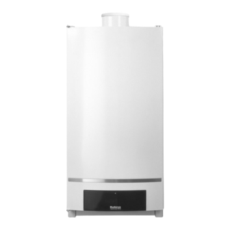
Buderus Logamax plus GB162 Applications Manual
Gas condensing boiler
Hide thumbs
Also See for Logamax plus GB162:
- Technical manual (172 pages) ,
- Applications manual (88 pages) ,
- Installation instructions manual (12 pages)
Advertisement
Quick Links
CAUTION!
Before putting the boiler into operation read this manual carefully.
WARNING!
Improper installation, adjustment, alteration, service or maintenance
can cause injury, loss of life or property damage. Refer to this manual.
For assistance or additional information consult a qualified installer,
service agency or the gas supplier.
CAUTION!
The operating manual is part of the documentation that is delivered to
the installation's operator. Go through the information in this manual
with the owner/operator and make sure that he or she is familiar with
all the necessary operating instructions.
Advertisement

Summary of Contents for Buderus Logamax plus GB162
- Page 1 CAUTION! Before putting the boiler into operation read this manual carefully. WARNING! Improper installation, adjustment, alteration, service or maintenance can cause injury, loss of life or property damage. Refer to this manual. For assistance or additional information consult a qualified installer, service agency or the gas supplier.
- Page 9 MCM10 Front Panel Off: No power / internal error MCM10 On: Standard operation Off: Pump off On: Pump on Off: Switching contact not activated Blinking: System fault (example : system pressure too low or error in the heating appliance(s)) Off: No communication On: Communication between MCM10 and the previous MCM10.
- Page 10 120V 120V Printed PE N L PE N L PE N L NO C NC Circuit Board Input Mains Output Mains System Alarm / Error 120V 120V Supply Supply to Pump output 120V following PE N L PE N L PE N L NO C NC 0 ..
- Page 22 Do 06.07. 2008 4:45h 71.9 ° Room...
- Page 23 Do 06.07. 2008 4:45h Standard display 71.9 ° Operation modes Room Switching program Summer/winter threshold Summer/winter time DHW temperature Holiday Party function Pause function Thermally desinfection Do 06.07. 2008 4:45h Quick operation 71.9 ° Room Settings Diagnosis Servicing Reset...
- Page 24 RC35 ways of controlling: outside temperature room temperature °F (°C) °F (°C) (100) (100) (80) (80) (60) (60) (40) (40) (20) (20) offset room temperature outside temperature RC35 Outside temperature damping Outside temperature controlled °F °C 78 (26) 75 (24) 72 (22) 68 (20) 64 (18)
- Page 25 RC35 Changing set point Outside temperature controlled 72° F 68°F 167 °F Setpoint (22° C) Setpoint (20°C) (75 °C) Setpoint 64.4°F (18°C) (-10 °C) (20 °C) 14 °F 68 °F Outside temperature...
- Page 26 RC 35 Max. & min. flow temperature Outside temperature controlled max. min. 14 °F 68 °F (-10 °C) (20 °C) Outside temperature RC 35 Max. & min. flow temperature Room temperature controlled max. (e.g. 75°C) 167°F min. (e.g. 25°C) 77°F Offset room temperature RC 35 Room influence Room temperature to low...
- Page 27 RC 35 room control unit Wall Mounting Bracket 18AWG 18AWG Connection to EMS (boiler) * Connection * If room sensor is not used, leave factory to external installed jumper in place. room temperature sensor Ground yel/grn must not be used as a control line.
- Page 29 18AWG 120 V 60Hz 18AWG 18AWG 18AWG 14AWG, 14AWG, Max. 5A Max. 5A Main power supply 120 V 60Hz Valve actuator motor Ground yel/grn must not be used as a control line. run time:...
- Page 30 14AWG 120 V 60Hz 14AWG, Max.5A 18AWG 18AWG 18AWG Main power zone low loss 120 V 60Hz header Ground yel/grn must not be used as a control line.
- Page 31 14AWG 120 V 60Hz 18AWG 18AWG 18AWG 18AWG 14AWG, Max. 1A Main power 120 V 60Hz tank Ground yel/grn...


Need help?
Do you have a question about the Logamax plus GB162 and is the answer not in the manual?
Questions and answers