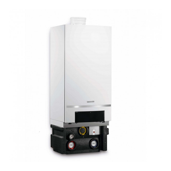
Buderus Logamax plus GB162-100 User Manual
Condensing gas boiler
Hide thumbs
Also See for Logamax plus GB162-100:
- Instructions manual (16 pages) ,
- Replacement instructions manual (12 pages) ,
- Service instructions manual (100 pages)


Need help?
Do you have a question about the Logamax plus GB162-100 and is the answer not in the manual?
Questions and answers