Saab R5 Supreme Operation & Installation Manual
Hide thumbs
Also See for R5 Supreme:
- Operation & installation manual (114 pages) ,
- Instruction (4 pages) ,
- Installation short instruction (4 pages)
Table of Contents
Advertisement
Quick Links
Download this manual
See also:
Instructions
Advertisement
Table of Contents
Troubleshooting

Subscribe to Our Youtube Channel
Related Manuals for Saab R5 Supreme


Summary of Contents for Saab R5 Supreme
-
Page 1: Navigation System
Saab TransponderTech R5 SUPREME Navigation System OPERATION & INSTALLATION MANUAL... - Page 2 This page is intentionally empty...
-
Page 3: Safety Instructions
The entire contents of this manual and its appendices, including any future updates and modifications, shall remain the property of Saab TransponderTech AB at all times. The contents must not, whether in its original form or modified, be wholly or partly copied or reproduced, nor used for any other purpose than the subject of this manual. - Page 4 SUPREME - Navigation System Contact Information For installation, service and technical support please contact your local Saab TransponderTech representative. A list of dealers and service stations can be found on the corresponding product page at www.saabgroup.com/transpondertech SYSTEM OVERVIEW 7000 118-301, A3...
-
Page 5: Table Of Contents
Installation Cables ....................13 System interconnection overview ............... 17 Installation Procedure ..................19 Mount the R5 SUPREME Control and Display Unit (CDU) ......... 20 Mount the R4 Navigation Sensor ................. 24 Mount the GPS or DGPS Navigation Antenna ............ 25 Mount the R5 NAV Junction Box (if applicable) .......... -
Page 6: System Overview Page
SUPREME - Navigation System Slave Displays and Redundant Systems ......... 104 R5 SUPREME Navigation System with Slave Display ........104 Redundant Navigation Systems ................ 107 Synchronized Items .................... 108 Software Upgrade ..............110 Upgrade Software in R5 SUPREME CDU ............110 Technical Specifications ............ -
Page 7: System Overview Page
SUPREME - Navigation System 14.4 R5 NAV Junction Box Physical Size and Mechanical Drawing ....... 153 15 Appendix B - License ..............154 15.1 Copy of the GNU General Public License ............154 SYSTEM OVERVIEW 7000 118-301, A3 Page 7... -
Page 8: System Overview
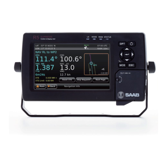
The R5 CDU has a seven inch colour touch display and provides a graphical interface to the system. Via the R5 SUPREME CDU it is possible to create, edit and modify routes and waypoints, navigate following a route, plot the route, view sensor data, configure the system as well as supervise the system status. -
Page 9: Main Features
Synchronization of waypoint/route database and settings with external R5 Navigation systems in redundant installations. Support for additional view only R5 SUPREME CDUs connected in slave mode. Input and output of IEC 61162-1 sentences configurable on sentence level and per port, providing control over interpreted, ignored and transmitted sentences. -
Page 10: Unpacking Equipment
SUPREME - Navigation System INSTALLATION Unpacking the Equipment Each delivery can be different depending on what options and accessories are ordered. The R5 SUPREME Navigation System may consist of one or several of the following parts: Name Part number Qty. - Page 11 (Transponder to AIS Junction Box) R5 AIS Junction Box 7000 118-120 (For combined AIS/NAV configuration) VHF Antenna BA 1012 7000 000-077 (for R5 SUPREME AIS Transponder) AT575-68 GPS Antenna 7000 000-135 (for R5 SUPREME AIS Transponder) MA700 GPS Antenna, incl. 10m cable 7000 000-485...
-
Page 12: Equipment Installation Environment
SUPREME - Navigation System Equipment Installation Environment The table below lists the IEC 60945 equipment classification for the system. Name Part number IEC 60945 installation category R5 SUPREME CDU 7000 118-530 Protected R5 NAV Junction box 7000 118-121 Protected R4 GPS Navigation Sensor... -
Page 13: Installation Cables
SUPREME - Navigation System Installation Cables The following cables are used to install the standard R5 SUPREME Navigation System. 2.3.1 R5 Signal Cable DSUB-OPEN Marking: 7000 118-078, C1 Application: R5 CDU I/O port to open ends Type: Shielded Twisted Pair 24 x 0.33 mm... - Page 14 SUPREME - Navigation System 2.3.2 R5 Signal Cable DSUB-DSUB (used with R5 NAV Junction Box) Marking: 7000 118-286 Application: R5 CDU I/O port to R5 NAV Junction box. Type: Shielded Twisted Pair x 0.33 mm Length: Diameter: 11 mm Connector: 2 x 26-pole H.D.D-SUB (female to male) Flame retardant: IEC60332-1...
- Page 15 SUPREME - Navigation System 2.3.4 R4 Navigation Sensor Power and Data Cable Marking: 7000 109-011 Application: R4 Sensor power and data port to open end. Type: 9-Pair x 0.25 mm Shielded Length: Connector: ConXall, Maxi-Con-18pin (male) Cable colour White Green Brown Brown/Green Yellow...
- Page 16 SUPREME - Navigation System 2.3.6 R4 Navigation Sensor GPS Antenna Cable (Not supplied by Saab TransponderTech) Type: See section 2.5.2 Length: See section 2.5.2 Connector: TNC (Male) 2.3.7 R5 SUPREME Ethernet Cable Type: Cat-7, LSZH-FR, IEC 60332-1 Length: Diameter: 6,5 mm...
-
Page 17: System Interconnection Overview
SUPREME - Navigation System System interconnection overview The R5 Navigation System can be set up in a number of different ways. As a standalone navigation system o One CDU unit, one sensor, one antenna, optional nav junction box As a Combined Navigation and AIS system o Same as above, plus a transponder with additional GPS and VHF antennas and an AIS junction box. - Page 18 SUPREME - Navigation System 2.1.1 Standalone R5 NAV with Junction Box The R5 Navigation system is available in a GPS or in a DGPS system configuration. The DGPS system features a R4 Navigation sensor and antenna different from the GPS system. In addition it is possible to do the installation with or without the R5 NAV Junction box.
-
Page 19: Installation Procedure
Connect all external systems and sensors to the R5 NAV Junction Box b. Mount the R5 NAV Junction Box c. Connect the R5 SUPREME CDU and the R4 Navigation Sensor to the R5 NAV Junction box 6) If R5 NAV Junction box is NOT used: a. -
Page 20: Cdu Location
2.3.1 CDU Location The R5 SUPREME CDU should be mounted close to the position from which the ship is normally operated, preferably on the bridge console close to the conning position. When mounting the R5 SUPREME CDU, please consider the following: The temperature and humidity should be moderate and stable, +15ºC to +35ºC... - Page 21 SUPREME - Navigation System 2.3.2.2 Panel Mount Panel mounting will reduce bridge clutter and reduce the space needed for installation.. A cutout fitting the CDU profile must be made. See Chapter 14 for dimensions. The CDU is fastened in place using the pin screw nut and washer nut from the included mounting kit 7000 118-315.
- Page 22 The CDU can be attached to the panel mount frame using the mounting kit 7000 118-315 included with the R5 CDU. Figure 3 – R5 SUPREME CDU, Mounting frame panel mount The cutout dimensions may need to be increased somewhat compared to the R4 MKD cutout, as the R5 CDU is slightly wider.
- Page 23 SUPREME - Navigation System 2.3.3 R5 CDU clearance area Leave a clearance around the R5 NAV Junction Box to facilitate service and installation. below figure minimum recommended clearance area (measurements in mm). Figure 4 – CDU Gimbal mount clearance Figure 5 CDU Panel mount clearance INSTALLATION 7000 118-301, A3 Page 23...
-
Page 24: Mount The R4 Navigation Sensor
SUPREME - Navigation System Mount the R4 Navigation Sensor 2.4.1 Sensor Location When mounting the R4 Navigation Sensor, please consider the following: Mount the unit so that the LEDs can be observed if needed for troubleshooting purposes. The temperature and humidity should be moderate and stable, +15ºC to +35ºC. (Operating temperature: -30ºC to +70ºC.) Select a location away from excessive heat sources. -
Page 25: Mount The Gps Or Dgps Navigation Antenna
Note: Once the system has been correctly mounted and connected, it is possible to monitor the R4 Navigation Sensor receiving performance via the graphical interface of the R5 SUPREME CDU. This information can be used to locate the optimum placement of the antenna. This is further described in section 5.11.3. - Page 26 SUPREME - Navigation System Type Attenuation @ 1.5 Weight (kg/100m) (mm) GHz (dB/m) RG 58 RG 400 4.95 RG 223 5.40 RG 214 0.35 10.8 18.5 RG 225 10.9 23.3 Table 8 – GPS Antenna Cables For optimum performance of the R4 Navigation Sensor, 12 dB should remain after subtraction of cable loss from the antenna pre-amplifier gain.
- Page 27 SUPREME - Navigation System Secure the cable properly, near the cable ends. 2.5.4 Grounding The MGA-2 and MGL-4 antennas do not require any antenna ground connection INSTALLATION 7000 118-301, A3 Page 27...
-
Page 28: Mount The R5 Nav Junction Box (If Applicable)
SUPREME - Navigation System Mount the R5 NAV Junction Box (if applicable) For easy installation of the R5 SUPREME Navigation System, the R5 NAV Junction Box can be used to connect the R5 CDU to the R4 Navigation Sensor. The junction... - Page 29 SUPREME - Navigation System Figure 7 – Clearance Area for R5 AIS / NAV Junction boxes INSTALLATION 7000 118-301, A3 Page 29...
- Page 30 SUPREME - Navigation System 2.6.3 Junction box Mounting It is recommended to connect external cables to the Junction box before mounting the box to a surface. Open the lid of the R5 NAV Junction Box. Fix the box on an appropriate surface/place with using the screw holes on the four feet of the junction box.
- Page 31 Relay Figure 8 – Installation with R5 NAV Junction Box 1. Connect the R5 SUPREME CDU to the junction box by using the R5 Signal Cable, DSUB-DSUB and the R5 Power Cable, Connect the R4 Navigation Sensor to the junction box by using the R5 NAV Sensor Cable.
-
Page 32: System Interconnection Without R5 Nav Junction Box
SUPREME - Navigation System System interconnection without R5 NAV Junction box (D)GPS Antenna R4 GPS Navigation Sensor or R4 DGPS Navigation Sensor R5 Signal Cable DSUB-OPEN R4 Nav Signal and Power Cable R5 Power Cable 24 VDC/2A 24 VDC/1A External fuse External fuse User User... - Page 33 SUPREME - Navigation System 2.7.3 Connect R5 CDU Sensor port to R4 Navigation Sensor R4 Navigation Sensor Signal and Power Cable R5 Signal Cable DSUB-OPEN Grey/Pink (RX B) Purple (TX B) Black (TX A) Red/Blue (RX A) White (TX B) Yellow (RX B) Brown (TX A) Green (RX A)
-
Page 34: Electrical Installation
The R5 SUPREME CDU is designed to operate on 12-24 VDC. The nominal power used is 13 W. The SUPREME CDU shall be externally fused (slow blow fuse) with a 5A fuse. The R5 NAV Junction Box has built in fuses for both the R5 SUPREME CDU and the R4 Navigation Sensor. 2.8.2... - Page 35 SUPREME - Navigation System 2.8.2.3 User Port 2 The port can only be used to output data from the R5 SUPREME Navigation System to external equipment. The TX signals of the port shall be connected to the RX signals of the external equipment.
- Page 36 User Port 3 and User Port 4 on the R5 SUPREME CDU are high-speed ports with isolated power and ground. They can be used to interface equipment in a ―high- speed craft‖...
-
Page 37: Concepts And Terminology
The RAIM status can be one of safe, caution and unsafe, and is indicated by the RAIM LED on the front of the R5 SUPREME CDU. If the calculated range error is larger than the currently used RAIM accuracy level, the RAIM status will be ―unsafe‖ and indicated with a red light on the RAIM LED. - Page 38 SUPREME - Navigation System The navigation algorithm is the algorithm used for calculating the course to steer to reach the next waypoint. It is also used for calculating the distance to the waypoint. The navigation algorithm can be either great circle or rhumb line. Great Circle Navigation The great circle navigation algorithm calculates a course line that is the shortest path between two points on the surface of the earth.
-
Page 39: Configuration
R5 SUPREME Navigation System is fully functional. Configuration Wizard The first time the R5 SUPREME CDU is started, a configuration wizard will be shown. This wizard is a helpful guide to configure the basic functionality of the R5 SUPREME System. - Page 40 4.1.4 Select CDU Master (Slave Mode Only) If the R5 SUPREME CDU is configured to be used as a slave display to an existing R5 SUPREME Navigation system, the master CDU must be selected on the LWE network in order to receive GPS data and synchronize waypoints, routes and configurations.
-
Page 41: Configuration Parameters
4.1.5 Connection View This view is shown while the R5 SUPREME CDU connects to external equipment and initializes the system. When the initialization is complete the R5 SUPREME CDU will automatically switch to the Position view when configured as a Navigation System. - Page 42 SUPREME - Navigation System Waypoint Pass Criteria The criteria that should be used to determine if a waypoint has been passed or not. Refer to chapter 3 for more information. If the Waypoint Pass Criteria is set to ―Distance‖, this Waypoint Pass Distance parameter specifies the distance that should be used to determine if the waypoint has been passed or not.
- Page 43 Navigation Sensor or the name of the next waypoint is to be displayed in the status bar at the upper left corner of the R5 SUPREME CDU. Local Time Zone Offset Output The Output in ZDA parameter defines if the local time...
- Page 44 SUPREME - Navigation System 4.2.2 This view is accessed by pressing Main Menu Configuration GPS / DGPS Parameter Name Description Elevation Mask This parameter sets the elevation cutoff mask angle, in degrees, for the GPS. Any satellites below this mask angle will be ignored, even if available.
- Page 45 SUPREME - Navigation System The setting of this parameter depends upon the expected dynamics of the vessel. If a ship is highly dynamic, this value should be set to a lower value since the filtering window needs be shorter in time, resulting in a more responsive measurement.
- Page 46 SUPREME - Navigation System PRN Search Mode Change between Automatic or Manual search mode. In Manual search mode, the R4 Navigation sensor will try to acquire signals from satellites with id (PRN) numbers input by the parameters PRN 1 and PRN 2 in the view.
- Page 47 SUPREME - Navigation System frequency mode parameter is set to manual. Valid frequencies are between 283.5 and 325 KHz, at 0.5 kHz intervals. This parameter is only available when Tuning Mode is set to manual. Bit Rate Mode The Bit Rate Mode parameter sets the bit rate mode to either Automatic or Manual.
- Page 48 4.2.6 Visual Settings The backlight for the LCD, LED‘s and the buttons of the R5 SUPREME CDU can be controlled manually or automatically using the light sensor on the front of the CDU. The default value of the LCD backlight is 80% which corresponds to approximately 550...
- Page 49 This parameter is only available when the ―Dimming Mode‖ parameter is set to ―Manual‖. This parameter can also be changed by holding down the PWR button on the front of the R5 SUPREME CDU and then press the button ―Dim Backlight‖. LCD Backlight Controls the maximum LCD backlight level in percent.
- Page 50 Time Zone This parameter defines if the times that are displayed in the R5 SUPREME CDU should be in UTC or LOC (local) time. If local time is chosen, the offset from UTC must be specified with the three parameters listed below.
- Page 51 R5 SUPREME CDU and a popup dialog will appear. There are also two parameters that decide how the acknowledge alarm function should affect the system.
- Page 52 Own CDU Settings (Network) This view is accessed by pressing Main Menu Configuration Interface Network Own CDU Settings Parameter Name Description CDU IP Address The Internet Protocol (IP) address of the R5 SUPREME CDU. CONFIGURATION 7000 118-301, A3 Page 52...
- Page 53 The unique ID that is used on the Light Weight Ethernet network. For example if this parameter is set to ―3141‖ the R5 SUPREME CDU will transmit messages on the LWE network with the LWE ID ―GP3141‖. This ID must be unique for all equipment connected to the same LWE network.
- Page 54 SUPREME - Navigation System Use Manual Offset If yes, the manually specified offset is added to the reported depth (regardless from which sentence it is taken). Manual Offset Specifies the size of the manual offset for depth. Manual Offset Sign Specifies the sign of the manual offset.
- Page 55 It is also possible to output correction data from the internal DGPS beacon receiver in RTCM format on User port 2. This function is available only if the R5 SUPREME CDU is used together with an R4 DGPS Navigation Sensor with routing software version 1.07 or higher.
-
Page 56: Operation
The easiest way to navigate in menus, lists and edit fields in the R5 SUPREME CDU is by using the touch interface. However, the arrow keypad and ENTER button can also be used to control the R5 SUPREME CDU in e.g. rough seas. The arrow keypad (< > and ∧ ∨) is OPERATION... - Page 57 ENTER button which is used to select the highlighted choice in a menu, list or edit control. 6. PWR The power button on the R5 SUPREME CDU is used to turn off the display and can also be used to quickly change the settings for backlight of LCD, buttons and LED‘s. A quick press of the PWR button will turn off all backlight but the R5 SUPREME CDU will still be running.
-
Page 58: Leds On R4 Navigation Sensor
Change Settings of a Parameter Several of the views in the R5 SUPREME CDU contain parameters that can be edited. To edit a parameter, click on it using the touch interface. A virtual keyboard will appear where it is possible to enter data. - Page 59 SUPREME - Navigation System It is also possible to use buttons on the front of the R5 SUPREME CDU to select and change a parameter. Use the ARROW KEYPAD to select a parameter, currently selected parameter will be marked with an orange rectangle (See figure above). Press ENTER to popup the virtual keyboard.
-
Page 60: System Menus - Tree View
SUPREME - Navigation System System Menus - Tree View OPERATION 7000 118-301, A3 Page 60... -
Page 61: Navigating In Menus
The R5 SUPREME Navigation System features alarm and alert pop-ups that can appear any time during operation. To acknowledge an alarm or alert message, click on the buttons of the pop-up using the touch display or use the arrow buttons on the R5 SUPREME CDU to navigate between buttons and press ENTER. -
Page 62: Status Bar
SUPREME - Navigation System Status Bar The top of the screen on the R5 SUPREME CDU always displays a summary of the system‘s status. Current time Status icons Current position Current RAIM Level Figure 26 – Status Bar The left part of the status bar can either show the current position in latitude and longitude, or the name of the next waypoint in the currently active route. -
Page 63: Navigate Menu
The RAIM LED on the front of the R5 SUPREME CDU will show the RAIM status. A green RAIM LED indicates safe state; the calculated position accuracy is better than the set accuracy level. - Page 64 Show Current Position Figure 28 – Position View The R5 SUPREME Navigation System will power up in the Position view. The Position view shows current position, speed over ground (SOG) and course over ground (COG) as reported by the R4 Navigation Sensor. The position is represented by latitude and longitude.
- Page 65 SUPREME - Navigation System When entering the Anchor Watch view, the following will be displayed: Figure 29 – Anchor Watch 5.8.2.1 Set Anchor Watch Alarm Distance To set the alarm distance, click on the alarm distance edit field (marked with an orange square in the picture above).
- Page 66 SUPREME - Navigation System Figure 31 – Anchor Watch Activated If the calculated range exceeds the alarm distance, the anchor watch alarm will be activated if configured to enabled in the Alarm Config view. If the range subsequently falls below the configured alarm distance, the anchor watch alarm condition will be deactivated.
- Page 67 SUPREME - Navigation System Press the button ―Show Position‖ to show Latitude and Longitude for each waypoint. Figure 33 – Active Route (Position) Press ―Show Acc. Dist.‖ to show the accumulated distance along the route to each waypoint. Figure 34 – Active Route (Accumulated Distance) Press ―Show WPT ETA‖...
- Page 68 SUPREME - Navigation System 5.8.3.1 Edit Active Route Press ―Edit Route‖ to enter the Edit Active Route view. This view is used to modify the active route. It displays all waypoints and legs in the active route, regardless if they are passed or not and including waypoints created when resetting cross-track error in the Navigation Info view.
- Page 69 SUPREME - Navigation System 5.8.4 Navigation Aid The Navigation Aid view presents fundamental navigation data and aids the user in navigating towards a waypoint and following a route. It presents information such as the bearing and range to the next waypoint, the ship‘s current course over ground (COG) and speed over ground (SOG) and current cross-track error (if sailing on a route).
- Page 70 SUPREME - Navigation System Figure 39 – Navigation Plot The next waypoint in the route is marked with a double circle and the currently active leg is shown in cyan colour. Other legs are shown in magenta colour and their waypoints are marked with a single circle.
- Page 71 SUPREME - Navigation System The left part of the Navigation Info view presents current navigation information. In Figure 40, an example of the Navigation Info view is shown. The information shown of the left side of the view is explained below: NAV RL to WP2 This means that the next waypoint in the current route is named ―WP2‖...
- Page 72 SUPREME - Navigation System 5.8.6.2 Skip Next Waypoint To skip the next waypoint and manually switch leg on the active route, press the button ‖Skip Waypoint‖. The right part of the Navigation Info view can show several different sub views which can be accessed by pressing the button ―Next Page‖.
- Page 73 SUPREME - Navigation System Figure 42 – Navigation Info View – WPT Info 5.8.6.5 Set and Drift The Set and Drift sub view show information received from heading sensors, depth sensors and speed sensors. This information together with SOG and COG is also used to calculate set and drift.
-
Page 74: Voyage Menu
Active Route view, described in section 5.8.3. The Route List view presents the routes currently stored in the R5 SUPREME CDU, and provides sub views to view and edit a route as well as creates new routes. The Route List view also contains functionality to delete routes and find a route by name. - Page 75 SUPREME - Navigation System Figure 46 – Route List 5.9.1.1 Sail a Route To start sailing a route, select the desired route in the Route List view and press the button ‖Sail Route‖. The Sail Route view will be shown. Figure 47 –...
- Page 76 SUPREME - Navigation System Figure 48 – Sail To View Either an existing waypoint can be used, or a new destination waypoint can be created. The new waypoint can be created by either specifying latitude and longitude or by specifying range and bearing from current position. To select or create a destination, press the button ―Select DEST‖.
- Page 77 SUPREME - Navigation System 6. Press ―Sail‖ in the Sail To view to start sailing towards the chosen destination. Figure 50 – Create New Waypoint – Latitude and Longitude Create a new waypoint by specifying bearing and range 1. Press the button ―Create New WPT‖ to show the Create New Waypoint view. 2.
- Page 78 SUPREME - Navigation System Figure 52 – Sail To View with Selected Destination 5.9.1.3 Edit a Route The Edit Route view enables the user to modify a route. It is possible to insert waypoints as well as whole existing routes into the route being edited. It is also possible to remove and edit waypoints and change settings such as navigation algorithm, RAIM level and XTE limit for each leg in the route.
- Page 79 SUPREME - Navigation System The Edit Route view can either show a list of all waypoints or a list of all legs in the route. When the waypoints are shown, it is possible to insert new waypoints or even complete routes into the existing route. When the legs are shown it is possible to change the navigation algorithm, RAIM level and XTE limit for each individual leg.
- Page 80 SUPREME - Navigation System 7. Press ―Save‖ in the Edit Route view to save changes in the edited route and exit to Route List view. Insert existing route into the route being edited 1. Make sure that the Edit Route view shows the waypoints (press ―Show WPs‖ if the legs are shown).
- Page 81 SUPREME - Navigation System 5. To change the RAIM accuracy level for the leg, press the ―RAIM Accuracy‖ droplist and choose ―RAIM Level‖. A new edit field will appear. Click on the ―Level‖ edit field to input a desired RAIM accuracy level in meters. 6.
- Page 82 SUPREME - Navigation System 5.9.1.4 Create a New Route The Create Route view is used to create a new route. A default name is supplied but should be changed to a descriptive name for the new route. A route can be created from the Route List view by pressing the button ―Create‖...
- Page 83 5.9.1.7 Upload Route to External Systems The R5 SUPREME CDU can send routes and associated waypoints to an external system via one of the serial User Ports or via the Light Weight Ethernet network. In order to upload routes and waypoints the user ports must be configured with correct baud rate and the sentence ―WPL/RTE (Upload)‖...
- Page 84 Waypoints are the basis for ship navigation. A waypoint is a position on the earth surface that is given a unique name and stored in the memory of the R5 SUPREME CDU. Waypoints can be entered in several different ways, and used for building routes as well as for direct navigation to a specific position.
- Page 85 SUPREME - Navigation System 5.9.2.2 Edit a Waypoint 1. Select the desired waypoint in the list. 2. Press the button ―WPT‖ followed by ―Edit‖. 3. Press the ―Name‖ edit field to edit the name of the waypoint. 4. Press the ―LAT‖ edit field to edit the latitude of the waypoint. 5.
- Page 86 5.9.2.7 Upload Waypoints to External Systems The R5 SUPREME CDU can send waypoints to an external system via one of the serial User Ports or via the Light Weight Ethernet network. In order to upload waypoints, the user ports must be configured with correct baud rate and the parameter ―WPL/RTE (Upload)‖...
- Page 87 SUPREME - Navigation System 5.9.2.8 Delete a Waypoint 1. Select the waypoint to be deleted in the waypoint list 2. Press the button ―WPT‖ followed by ―Delete‖. 3. A confirmation popup will appear, press ―Yes‖ to delete the waypoint. It is NOT possible to delete a waypoint that is used by any route.
- Page 88 SUPREME - Navigation System Figure 68 – Create Time Alert View 2. To edit the alert text that is shown in the popup, press the ―Alert Text‖ edit field. A virtual keyboard will appear. Enter the desired alert text and press enter on the virtual keyboard.
-
Page 89: Tidal Predictions
5.10 Tidal Predictions The R5 SUPREME CDU can be used for calculation of tidal predictions based on user input of data from the Admiralty Tide Tables published by the U.K Hydrographic Office. The user is required to input data for the specific port and select the point in time for which the prediction is to be calculated. - Page 90 Figure 70 – Tide Plot with No Port Selected 2. Click on the button ―Select Location‖ to enter the Port List view. This view will show all the ports that have been entered in the R5 SUPREME CDU. Figure 71 – Port List 3.
- Page 91 SUPREME - Navigation System 4. Some ports have season or fortnightly variations in mean level and harmonic constants. If so, such variations can be input by selecting ―Use Table…‖ in the corresponding drop list for the parameter. Figure 73 – Add Port – Input Seasonal Variations A new view will be shown where the variation values from the ―Admiralty Tide Tables‖...
- Page 92 SUPREME - Navigation System variations as required for some stations can be entered as described below. ML Seasonal Seasonal corrections to the mean level value as defined for some ports. If so, this parameter shall be set to ‗Use Table…‘ which will open a new view where values for each month can be input in accordance with the corrections listed in ATT part III.
- Page 93 SUPREME - Navigation System 1. Enter the Tide Plot view by pressing Main Menu Voyage Tide 2. Click on the button ―Select Location‖ to enter the Port List view. 3. Select the desired port in the port list and click on the button ―Use Port‖. The Tide Plot view is shown with a graphical prediction for the current day or a previously selected date.
- Page 94 ‗UTC‘. If a local time frame is used, times will be denoted ‗LOC‘. This is in analogy with how all times generally are treated by the R5 SUPREME CDU. Thus, it is important to realize that a tide displayed in ‗LOC‘ time is not necessarily the local time in the port (defined by the ‗Zone‘...
-
Page 95: Status Menu
SUPREME - Navigation System Figure 78 – Edit Port, Zone Setting Figure 79 – Time Zone Settings for the R5 SUPREME CDU 5.11 Status Menu 5.11.1 GPS / DGPS Overview Figure 80 – GPS/DGPS Overview OPERATION 7000 118-301, A Page 95... - Page 96 The current RAIM status result which can be Safe, Unsafe or Caution. The RAIM status is also indicated by RAIM LED on the front of the R5 SUPREME CDU. A green LED corresponds to the safe state, yellow to caution state and red to unsafe state.
- Page 97 SUPREME - Navigation System source, the satellite used for applied corrections is also displayed below the list. ‗No SBAS Satellite In Use‘ will be displayed if a correction source another than SBAS is selected. Figure 81 – SBAS Info 5.11.3 Satellite Info The Satellite Info view shows information relating to GPS satellites that the R4 Navigation Sensor is receiving or expecting to receive signals from.
- Page 98 SUPREME - Navigation System 5.11.5 Currently Selected Beacon The Currently Selected Beacon view shows information related to the R4 DGPS Navigation Sensor‘s beacon reception. The view is only accessible if an R4 DGPS Navigation Sensor is used as navigation sensor. The following information is displayed: Figure 84 –...
- Page 99 SUPREME - Navigation System 5.11.6 Beacon Database The Beacon Database view is used for inspection of the radio beacon station database stored in the R4 Navigation Sensor. The Beacon Database view is accessed from Main Menu Status Navigation GPS / DGPS Beacon Database but is only available when using an R4 DGPS Navigation Sensor and the parameter ―Beacon Database‖...
- Page 100 (#1 and #2) are available as well as a ‗total‘ trip log. The trip logs accumulate travelled distance during the on time of the R5 SUPREME Navigation System. Trip logs #1 and #2 are individually resettable and will also provide accumulated time moving and average speed since last reset.
- Page 101 5.11.10 SW/HW Info This view is accessed from Main Menu Status SW/HW Info and displays the software and hardware revisions for the R5 SUPREME Navigation System. This information should always be provided when in contact with Saab TransponderTech support.
-
Page 102: Dgps Messages (Dgps Version Only)
Figure 91 – DGPS Message View 5.13 Update Software The software in the R5 SUPREME CDU is easily upgraded via the USB Host interface located behind the front hatch. To perform a software update, follow the instructions in the Update Software view which can be accessed from Main Menu Maintenance Update Software. - Page 103 SUPREME - Navigation System Figure 92 - Update Software OPERATION 7000 118-301, A Page 103...
-
Page 104: Slave Displays And Redundant Systems
Please see chapter 12 for schematics of alternate setups. R5 SUPREME Navigation System with Slave Display It is possible to connect one or more slave displays to an existing R5 SUPREME Navigation System. The R5 SUPREME CDU that is connected to an R4 Navigation Sensor will... - Page 105 GLL2 (NMEA 2.3) Set DTM to every ten seconds. 5. Power up the R5 SUPREME CDU slave display in Wizard mode. If the R5 SUPREME CDU is a new unit it will automatically start in this mode. If the R5 SUPREME CDU is already configured, go to Main Menu Maintenance ...
- Page 106 SUPREME - Navigation System 7. Make sure that the R5 SUPREME CDU slave has a configured IP Address and a unique LWE Id. Figure 97 – Slave, Network Configuration 8. The R5 SUPREME CDU slave must now select the master R5 SUPREME CDU in the Select CDU Master view.
-
Page 107: Redundant Navigation Systems
Figure 100 – Master and Slave CDU in Sync Redundant Navigation Systems In a redundant setup, each R5 SUPREME CDU is connected to its own R4 Navigation Sensor that provides the GPS data. In addition, the R5 SUPREME CDU is also connected... -
Page 108: Synchronized Items
6.3. If an irresolvable conflict occurs, a sync popup message will appear where the user must manually select the R5 SUPREME CDU ―with the correct information‖ i.e. the unit that all other units should copy their configuration, waypoint and route databases from. - Page 109 SUPREME - Navigation System Default Navigation Algorithm Default Cross Track Error Limit Approach Distance Approach Time Average SOG Time Parameters such as baud rates, NMEA sentence output on the user ports and LWE network and display settings are NOT synchronized between the systems. SLAVE DISPLAYS AND REDUNDANT SYSTEMS 7000 118-301, A Page 109...
-
Page 110: Software Upgrade
SUPREME - Navigation System SOFTWARE UPGRADE Upgrade Software in R5 SUPREME CDU The R5 SUPREME CDU is easily upgraded via the USB host interface located behind the front hatch. To upgrade the software in the R5 SUPREME CDU, perform the following steps: Unzip the R5 SUPREME CDU upgrade package in the root folder of an USB memory stick. -
Page 111: Technical Specifications
SUPREME - Navigation System TECHNICAL SPECIFICATIONS R5 SUPREME CDU 8.1.1 Physical Dimensions: Height: 140 mm Width: 255 mm Depth: 85 mm Weight: 1.8 kg 8.1.2 Electrical Input Voltage: 24 VDC Power Consumption: 13 W 8.1.3 Environmental -15˚C to +55˚C (Operational) Temperature: -30˚C to +80˚C (Storage) -
Page 112: R4 Navigation Sensor
SUPREME - Navigation System R4 Navigation Sensor 8.2.1 Physical Dimensions: Height: 39 mm Width: 128 mm Depth: 137 mm Weight: 0.5 kg Antenna Connector: TNC-Female 8.2.2 Electrical Input Voltage: 24V DC (10 to 32V DC) Nominal Power: 2.0 W (GPS Version) 2.7 W (DGPS Version) Nominal Current: 0.08A @ 24 VDC input (GPS Version) - Page 113 SUPREME - Navigation System 8.2.4 Internal GPS Receiver Type: L1, C/A code, 12 channel, parallel tracking (2 channels dedicated for SBAS tracking) Update Rate: 5 Hz max Position Accuracy: < 2 m, Horizontal, 2 sigma (95%), DGPS < 5 m, Horizontal, 2 sigma (95%), GPS 8.2.5 Internal Beacon Receiver (DGPS Version only) Channels:...
-
Page 114: R5 Nav Junction Box
SUPREME - Navigation System R5 NAV Junction Box 8.3.1 Physical Dimensions: Height: 72 mm Width: 270 mm Depth: 200 mm Weight: 0.75 kg 8.3.2 R5 NAV Junction Box Alarm Relay Max switching current: Max switching voltage s: 220 VDC or 250 VAC Max switching power: 60W (DC) or 62.5 VA (AC) resistive load 8.3.3... -
Page 115: Troubleshooting
R5 SUPREME Navigation System. Troubleshooting with the CDU Front Panel LED’s It is very fast and effective to use the LED‘s to verify the status of the R5 SUPREME CDU. This should always be the first step in the troubleshooting. 8.4.1... -
Page 116: Troubleshooting With Alarm Messages
$GPALR,hhmmss.ss,xxx,A,A,c-c: Position Data Lost: Alarm is Active and Acknowledged $GPALR,hhmmss.ss,xxx,A,V,c-c: Position Data Lost: Alarm is Active and Unacknowledged The alarms that can occur in the R5 SUPREME Navigation System are listed below: 8.5.1 NAV: HDOP Limit Exceeded (ID 151) This alarm is active when the HDOP (horizontal dilution of precision) exceeds 4.0. - Page 117 The alarm is active when the display is not able to configure or receive the current configuration from the R4 Navigation Sensor. 8.5.5 NAV: GPS Connection Lost (ID 155) This alarm is active if the communication between the GPS and the R5 SUPREME CDU does not work. 8.5.6 NAV: XTE Limit Exceeded (ID 156) This alarm is active if the current cross-track error is greater than the configured cross- track error limit.
-
Page 118: Troubleshooting Via The Cdu
10%. Troubleshooting via the CDU There is a lot of information and data accessible via the R5 SUPREME CDU that can be useful for troubleshooting, and that can help finding a presumed problem. The following items are just a few examples of what to look at. -
Page 119: Contacting Support
OEM partners and service stations can be found at our website, listed under the corresponding product. www.saabgroup.com/transpondertech. It is also possible to contact Saab TransponderTech‘s technical support if this is preferred. We recommend contacting us via email at support.transpondetech@saabgroup.com most accurate and detailed help. -
Page 120: Serial Communication Interfaces
Output Sentences The serial interfaces of the R5 SUPREME Navigation System supports transmission of the sentences described in the tables below. All sentences can be transmitted on User Port 1 and 2, while User Port 3 and 4 support most sentences. - Page 121 SUPREME - Navigation System once per second only. Messages marked with ―-― are not supported on that port. Transmission of each sentence can also be disabled. Sentences containing position information (GGA, GLL, GNS and RMC) are possible to output with or without GPS antenna offset. Caution must be taken when enabling these sentences as it is possible to output position sentences with and without GPS antenna offset on the same port, this is not recommended.
- Page 122 SUPREME - Navigation System Sentence Description Port 1 & 2 Port 3 & 4 Recommended minimum navigation 1 Hz 1 Hz information Cross-track error, measured 1 Hz 1 Hz WPL/RTE Working routes and associated waypoint 1 Hz 1 Hz Working locations (see Note 4) WPL/RNN Working routes and associated waypoint...
-
Page 123: Interpretations Of Output Sentences
SUPREME - Navigation System 10 INTERPRETATIONS OF OUTPUT SENTENCES 10.1 Output Sentences, GPS All output sentences use GP as talker identifier. DTM – Datum Reference 10.1.1 $--DTM,ccc,a,x.x,a,x.x,a,x.x,ccc Field Format Name Comment --DTM Sentence Id Local datum Always W84 Local datum subdivision code Null field Lat offset, min Always zero... - Page 124 SUPREME - Navigation System GGA – Global Positioning System Fix Data 10.1.3 $--GGA,hhmmss.ss,llll.ll,a,yyyy.yy,a,x,xx,x.x,x.x,M,x.x,M,x.x,xxxx Field Format Name Comment --GGA Sentence Id hhmms UTC of position s.ss llll.ll Latitude yyyy.yy Longitude GPS quality indicator Satellites in use Horizontal dilution of precision Antenna altitude Units of antenna altitude, meter Geodial separation Units of geodial sep.
- Page 125 SUPREME - Navigation System GNS – GNSS fix data 10.1.5 $--GNS,hhmmss.ss,llll.ll,a,yyyy.yy,a,c—c,xx,x.x,x.x,x.x,x.x,x.x,a Field Format Name Comment --GLL Sentence Id hhmms UTC of position s.ss llll.ll Latitude yyyy.yy Longitude c—c Mode indicator Total number of satellites HDOP Antenna altitude, meter Geodial separation Age of differential corrections Differential reference station ID Navigational Status Indicator...
- Page 126 SUPREME - Navigation System GSA – GNSS DOP and active satellites 10.1.7 $--GSA,a,x,x.x,x.x,…,x.x,x.x,x.x,x.x Field Format Name Comment --GSA Sentence Id Mode Mode Satellite ID (1) Satellite ID (2) … … … Satellite ID (12) PDOP HDOP VDOP GNSS System ID GST –...
- Page 127 SUPREME - Navigation System GSV – GNSS satellites in view 10.1.9 $--GSV,x,x,xx,xx,xx,xxx,xx....,xx,xx,xxx,xx,h Field Format Name Comment --GSV Sentence Id Total number of messages Message number Total number of satellites in view Satellite ID number (Satellite 1) Elevation, degrees (Satellite 1) Azimuth, degrees true (Satellite SNR (Satellite 1) Fields for all...
- Page 128 SUPREME - Navigation System 10.1.11 VTG – Course over ground and ground speed $--VTG,x.x,T,x.x,M,x.x,N,x.x,K,a Field Format Name Comment --VTG Sentence Id Course over ground, degrees true Course over ground, degrees magnetic Speed over ground, knots Speed over ground, km/h Mode indicator 10.1.12 ZDA –...
-
Page 129: Output Sentences, Navigation
SUPREME - Navigation System 10.2 Output Sentences, Navigation All output sentences use GP as talker identifier. ALR – Alarm State 10.2.1 $--ALR,hhmmss.ss,xxx,A,A,c--c Field Format Name Comment --ALR Sentence Id hhmms UTC time of last condition s.ss change Alarm identifier number A = Threshold Alarm condition exceeded, V =... - Page 130 SUPREME - Navigation System APB – Heading/Track Controller (Autopilot) Sentence B 10.2.3 $--APB,A,A,x.x,a,N,A,A,x.x,a,c--c,x.x,a,x.x,a,a Field Format Name Comment --APB Sentence Id Status Status Magnitude of XTE Direction to Steer XTE units Status Status Bearing origin to destination c--c Destination waypoint ID Bearing, present position to destination Heading to steer to destination...
- Page 131 SUPREME - Navigation System BWC/BWR – Bearing and distance to waypoint 10.2.5 $--BWC,hhmmss.ss,llll.ll,a,yyyy.yy,a,x.x,T,x.x,M,x.x,N,c--c,a $--BWR,hhmmss.ss,llll.ll,a,yyyy.yy,a,x.x,T,x.x,M,x.x,N,c--c,a Field Format Name Comment --BWC Sentence Id --BWR hhmms UTC of observation s.ss llll.ll Waypoint latitude yyyy.yy Waypoint longitude Bearing, degrees true Bearing, degrees magnetic Distance, nautical miles c--c Waypoint ID Mode indicator...
- Page 132 SUPREME - Navigation System RMB – Recommended minimum navigation information 10.2.7 $--RMB,A,x.x,a,c--c,c--c,llll.ll,a,yyyy.yy,a,x.x,x.x,x.x,A,a Field Format Name Comment --RMB Sentence Id Status Cross track error, nautical miles Direction to steer L/R c--c Origin waypoint ID c--c Destination waypoint ID llll.ll Destination waypoint latitude yyyy.yy Destination waypoint longitude Range to destination, nautical...
-
Page 133: Output Sentences, Old Nmea Versions
SUPREME - Navigation System WPL – Waypoint location 10.2.9 $--WPL,llll.ll,a,yyyy.yy,a,c--c Field Format Name Comment --VPL Sentence Id llll.ll Waypoint latitude, N/S yyyy.yy Waypoint longitude, E/W c--c Waypoint identifier 10.2.10 XTE – Heading steering command $--XTE,A,A,x.x,a,N,a Field Format Name Comment --XTE Sentence Id Status Status... -
Page 134: Interpretations Of Input Sentences
SUPREME - Navigation System 11 INTERPRETATIONS OF INPUT SENTENCES Per default, any talker identifier is accepted. 11.1 Input Sentences ACK – Acknowledge alarm 11.1.1 $--ACK,xxx Field Format Name Comment --ACK Sentence Id Used Corresponds to ALR message Alarm identifier number for alarm to acknowledge DBT –... - Page 135 SUPREME - Navigation System HDG – Heading, Deviation and Variation 11.1.4 $--HDG,x.x,x.x,a,x.x,a Field Format Name Comment --HDG Sentence Id Used Magnetic sensor heading, Used degrees Magnetic deviation, degrees Used Magnetic variation, degrees Used HDT – Heading, True 11.1.5 $--HDT,x.x,T Field Format Name Comment...
-
Page 136: Input Sentences, Old Nmea Versions
SUPREME - Navigation System WPL – Waypoint location 11.1.7 $--WPL,llll.ll,a,yyyy.yy,a,c--c Field Format Name Comment --WPL Sentence Id Used llll.ll Waypoint latitude, N/S Used yyyy.yy Waypoint longitude, E/W Used c--c Waypoint identifier Used VHW – Water speed and heading 11.1.8 $--VHW,x.x,T,x.x,M,x.x,N,x.x,K Field Format Name... -
Page 137: Alternate System Setups
SUPREME - Navigation System 12 ALTERNATE SYSTEM SETUPS 12.1.1 Redundant Navigation Systems CAT5 Ethernet Front Hatch Front Hatch R4 GPS Navigation Sensor or R4 GPS Navigation Sensor or USB Host USB Host R4 DGPS Navigation Sensor R4 DGPS Navigation Sensor SDHC Card Reader SDHC Card Reader Pilot Plug (Used in AIS and... -
Page 138: Combined Ais And Navigation System Setup
For information about AIS functions and setup, please see the navigation system manual: 7000 118-300, R5 SUPREME AIS System manual. As with a standard R5 Navigation System installation, the R5 NAV Junction box can be omitted if open cables for the CDU and Navigation sensor are used together with a customer own solution for interconnection of the system. -
Page 139: R5 Combined With/Without Nav Junction Box
SUPREME - Navigation System 12.2.1 R5 Combined with R5 NAV Junction box R4 GPS Navigation Sensor or R4 DGPS Navigation Sensor Ethernet R5 CDU in Combined AIS and R5 Transponder NAV mode R5 NAV Sensor Cable R5 Power Cable R5 Signal Cable R5 Signal Cable External power 12-24 VDC R5 Signal Cable... -
Page 140: Electrical Interfaces
SUPREME - Navigation System 13 ELECTRICAL INTERFACES 13.1 CDU Interfaces: 13.1.1 CDU back: Ethernet port – RJ-45 100 MBit – IEC 61162-450 13.1.1.1 13.1.1.2 I/O port In/Out Signal Name Signal Type R5 Signal Cable DSUB-OPEN Sensor Port – TxB (+) RS422 White Sensor Port –... - Page 141 SUPREME - Navigation System In/Out Signal Name Signal Type R5 Signal Cable DSUB-OPEN General I/O 2 – In Binary White / Pink Binary Pink / Brown Binary White / Blue General I/O 0 – In Binary Brown / Blue General I/O 3 - Out Binary White / Red NOT CONNECTED...
- Page 142 SUPREME - Navigation System Figure 109 - CDU Pilot plug pin numbering Pilot plug Signal Type PIN 9 RS-422 GND PIN 1 RS-422 TX-A PIN 5 RS-422 RX-A PIN 4 RS-422 TX-B PIN 6 RS-422 RX-B Table 16 – CDU Pilot port signals 13.1.3 Secure Digital Card Reader Supports SD and SDHC cards with FAT32 file systems.
- Page 143 SUPREME - Navigation System 13.1.4 Electrical Characteristics of CDU Serial ports The serial ports in the R5 SUPREME CDU are the Sensor Port, User Port 3 and user Port 13.1.4.1 Output Drive Capacity Each serial port transmitter in the R5 SUPREME CDU can have a maximum of 25 listeners drawing 2.0 mA each.
-
Page 144: R4 Navigation Sensor Interfaces
SUPREME - Navigation System 13.2 R4 Navigation Sensor interfaces 13.2.1 Signal and Power port Connector: 18-pin circular ConXall female Signal types: In/Out Signal Name Signal Type R4 Sensor Signal and Power Cable Colour RS422 / User Port 1– RxA (-) White RTCM SC-104 System Port –... -
Page 145: Receiver End
SUPREME - Navigation System 13.2.3.2 Input Load Each listener draws less than 2 mA @ 2 V input voltage. 13.2.3.3 Termination The R5 NAV Junction Box has built in termination resistors. If needed, the termination resistors can be connected by flipping the respective termination switch in the junction box. - Page 146 SUPREME - Navigation System 13.2.4 Electrical Characteristics of R4 Navigation Sensor digital ports 13.2.4.1 Speed Log Out Port The Speed Log Out port provides a 50 ms long 5 V pulse with an interval corresponding to the ship‘s present speed, and system configuration. The speed pulse interval has a resolution of 50 ms, providing a resolution of 0.5 knots up to 10-20 knots depending on pulse rate and a working range up to 30 knots.
-
Page 147: R5 Nav Junction Box Interfaces
M20: Will fit 6-12 mm cables. For larger cables please unscrew the cable gland. 13.3.2 External Power: The R5 SUPREME Navigation System is designed to operate on 12-24 volts DC. The R5 NAV Junction Box shall be connected to an emergency power source. -
Page 148: Internal Circuit Board Layout
Terminal block for GPIO Out GPIO IN Terminal block for GPIO In ALARM RELAY Terminal block for NAV Alarm Relay Termination Switches for User 4, 3 and 1 D-SUB Connector for R5 Supreme CDU ELECTRICAL INTERFACES 7000 118-301, A Page 148... - Page 149 SUPREME - Navigation System D-SUB Connector for R4 Navigation Sensor 5A fuse for CDU 1A fuse for Navigation Sensor Table 1 – Terminals and Components Note 1: The item markings listed in Column 1 are not visible on the circuit board. The terminal markings should be used when referring to terminals.
-
Page 150: Mechanical Drawings
SUPREME - Navigation System 14 MECHANICAL DRAWINGS 14.1 CDU Physical Size and Mechanical Drawing Figure 114 – R5 SUPREME CDU Mechanical Drawing (mm) MECHANICAL DRAWINGS 7000 118-301, A Page 150... -
Page 151: Cdu Panel Mount Cutout Hole Dimensions
SUPREME - Navigation System 14.2 CDU Panel Mount Cutout Hole dimensions MECHANICAL DRAWINGS 7000 118-301, A Page 151... -
Page 152: Sensor Physical Size And Mechanical Drawing
SUPREME - Navigation System 14.3 Sensor Physical Size and Mechanical Drawing Figure 115 – R4 Navigation Sensor Measurements (mm) MECHANICAL DRAWINGS 7000 118-301, A Page 152... -
Page 153: R5 Nav Junction Box Physical Size And Mechanical Drawing
SUPREME - Navigation System 14.4 R5 NAV Junction Box Physical Size and Mechanical Drawing Figure 116 – R5 NAV Junction Box, Dimensions (mm) MECHANICAL DRAWINGS 7000 118-301, A Page 153... -
Page 154: Appendix B - License
SUPREME - Navigation System 15 APPENDIX B - LICENSE The R5 SUPREME CDU runs on a Linux operating system which is licensed with GNU General Public License. The source code of the linux kernel can be obtained by contacting Saab TransponderTech AB: Saab TransponderTech Låsblecksgatan 3... - Page 155 SUPREME - Navigation System Thus, it is not the intent of this section to claim rights or contest your rights to work written entirely by you; rather, the intent is to exercise the right to control the distribution of derivative or collective works based on the Program. In addition, mere aggregation of another work not based on the Program with the Program (or with a work based on the Program) on a volume of a storage or d istribution medium does not bring the other work under the scope of this License.
- Page 156 SUPREME - Navigation System This program is distributed in the hope that it will be useful, but WITHOUT ANY WARRANTY; without even the implied warranty of MERCHANTABILITY or FITNESS FOR A PARTICULAR PURPOSE. See the GNU General Public License for more details. You should have received a copy of the GNU General Public License along with this program;...
Need help?
Do you have a question about the R5 Supreme and is the answer not in the manual?
Questions and answers
Как создать маршрут