Saab R5 Operation & Installation Manual
Solid ais system
Hide thumbs
Also See for R5:
- Operation & installation manual (156 pages) ,
- Instruction (4 pages) ,
- Installation short instruction (4 pages)
Table of Contents
Advertisement
Advertisement
Table of Contents
Troubleshooting

Related Manuals for Saab R5


Summary of Contents for Saab R5
- Page 1 Saab TransponderTech SOLID AIS System OPERATION & INSTALLATION MANUAL...
- Page 2 This page is intentionally empty...
-
Page 3: Safety Instructions
Software This manual reflects the capabilities of the R5 SOLID AIS System with Software 1.0.11. If the system has been updated from this version, such change should be reflected on a label on the unit. - Page 4 Please refer to your local waste authority for information on return and collection systems in your area. Contact Information For installation, service, ordering info and technical support please contact your local Saab TransponderTech representative. A list of dealers and service stations can be found corresponding product page www.saabgroup.com/transpondertech.
-
Page 5: Table Of Contents
Unpacking the Equipment ..................11 Installation Cables ....................12 Installation procedure ..................12 Mount the R5 SOLID ..................... 13 Mount the R5 SOLID Transponder’s VHF antenna ..........17 Mount the R5 SOLID GPS Antenna ..............19 Electrical Installation .................... 21 System Configuration ................... 25 Operation.................. - Page 6 SOLID AIS System 4.21 GPS Status ......................50 4.22 View Raw Data ...................... 50 4.23 SW/HW Info ......................50 4.24 VHF Status ......................51 4.25 Communication Test .................... 51 4.26 Update Software ....................51 4.27 Restore Config ...................... 52 Software Upgrade................53 Technincal Specifications .............
- Page 7 SOLID AIS System 10 Glossary ..................80 10.1 Units ........................82 11 Appendix A – Inland ERI Ship Types ........... 83 12 Appendix B – License ..............85 12.1 Copy of the GNU General Public License ............85 THE AUTOMATIC IDENTIFICATION SYSTEM 7000 118-200, C2 Page 7...
-
Page 8: The Automatic Identification System
SART (Search and Rescue Transmitters) – Distress beacons for life rafts. An active SART unit will always be sorted on top of the target list in the R5 SOLID to accentuate its presence. NOTE: The R5 SOLID AIS SYSTEM can be operated in either Class A or Inland modes depending on user need. -
Page 9: System Overview
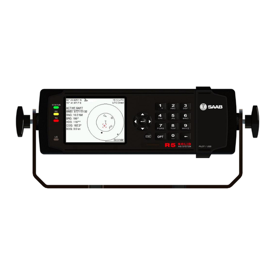
SYSTEM OVERVIEW Product Description The R5 SOLID AIS System (R5 SOLID from here on) consists of a transceiver radio unit, a GPS receiver, a controller unit and a colour LCD with a numerical keypad. The radio has three receivers, two tuneable TDMA receivers and one DSC receiver. The transmitter alternates its transmissions between the two operating TDMA). -
Page 10: Main Features
Possibility to generate Long Range AIS reply over satcom equipment such as Inmarsat C. In addition to the normal high (12,5W) and low (1W) power mode, the R5 SOLID has a 1W tanker mode in accordance with requirements for tanker operations in port. -
Page 11: Installation
SOLID AIS System INSTALLATION Unpacking the Equipment The R5 SOLID AIS System typically consists of the following parts: Name Part number Qty. R5 SOLID AIS Transponder 7000 118-501 SOLAS Class A & Inland AIS R5 Power Cable 2m 7000 118-077... -
Page 12: Installation Cables
Connector: TNC (Male) Installation procedure When installing the R5 SOLID, it is recommended to follow the steps described in this Installation Manual. Details of the installation procedure can be found in the coming sections of the Installation Manual. Recommended installation steps: 1. -
Page 13: Mount The R5 Solid
Mount the R5 SOLID 3.4.1 Location The R5 SOLID should be mounted close to the position from which the ship is normally operated, preferably on the bridge console close to the conning position. When mounting the R5 SOLID, please consider the following: ... - Page 14 SOLID AIS System 3.4.2 Physical Size and Mechanical Drawing Figure 2 – Gimbal Mount Figure 3 – Gimbal Mount (Bottom View) INSTALLATION 7000 118-200, C2 Page 14...
- Page 15 SOLID AIS System Figure 4 – Panel Mount Figure 5 – Panel Mount Front View INSTALLATION 7000 118-200, C2 Page 15...
- Page 16 SOLID AIS System Figure 6 – GPS Antenna – MA-700 Figure 7 – GPS Antenna – AT575-68 INSTALLATION 7000 118-200, C2 Page 16...
-
Page 17: Mount The R5 Solid Transponder's Vhf Antenna
Figure 8 – Combined VHF / GPS Antenna – AC Marine Mount the R5 SOLID Transponder’s VHF antenna The R5 SOLID, like any other ship borne transceiver operating in the VHF maritime band, may cause interference to a ship’s VHF radiotelephone. Because AIS is a digital system, this interference may occur as a periodic (e.g. - Page 18 SOLID AIS System the voice VHF installations used for main communication to avoid unnecessary interference. There should not be more than one antenna on the same level. The AIS VHF antenna should be mounted directly above or below the ship’s primary VHF radiotelephone antenna, with no horizontal separation and with a minimum of 2 meters vertical separation.
-
Page 19: Mount The R5 Solid Gps Antenna
Mount the R5 SOLID GPS Antenna The R5 SOLID shall be connected to a GPS antenna type MA-700, AT575-68 or a combined AC Marine GPS/VHF antenna. 5V DC is supplied through the antenna lead for the antenna preamplifier. - Page 20 SOLID AIS System high-power lines, such as radar or radio transmitter lines or the AIS VHF antenna cable. A separation of 1 meter or more is recommended to avoid interference due to RF-coupling. Crossing of antenna cables should be done at 90 degrees to minimise magnetic field coupling.
-
Page 21: Electrical Installation
Electrical Installation The protocol of the serial port interfaces is compliant to IEC 61162-1Ed.4 (2010-11). All serial ports in the R5 SOLID have the same capabilities with one exception, any Long Range equipment must be connected to the Long Range port. - Page 22 Schematics of a R5 SOLID Serial Transceiver Each of the RS422 serial interfaces on the R5 SOLID fulfils the requirements of IEC 61162-2 and IEC 61993-2. A detailed schematic of one of the serial ports in the R5 SOLID is shown below.
- Page 23 Tx (Transponder side) Rx (Transponder side) Not Connected Not Connected Not Connected Not Connected Not Connected Table 9 – 9-pin female D-sub 3.7.6 R5 Power Cable, 7000 118-077, A Signal Name Colour 24VDC positive Black INSTALLATION 7000 118-200, C2 Page 23...
- Page 24 The status of the blue sign can be controlled by input on the brown and orange wires of the R5 Power Cable. The status of the Blue Sign will be read by the R5 SOLID and output on the VHF data link when operating in “Inland Mode” (see section 4.4.16 for more details). Connect the blue sign switch to pin 3 (brown wire) and pin 4 (orange wire) of the R5 Power Cable together with an external parallel resistor.
-
Page 25: System Configuration
Ship dimensions and antenna positions. Refer to section 4.4.4 Main Menu Config Ship Dimensions for more information. If the R5 SOLID is operating in Inland mode, the following parameters also need to be configured: ENI, Unique European Ship Number ... - Page 26 R5 SOLID is fully functional. Check the Transmitted Own Ship Data view to make sure that the configured data is sent by the R5 SOLID on the VHF link, refer to section 4.10 “View Transmitted Own Ship Information” for more information. ...
-
Page 27: Operation
The R5 SOLID will also output binary messages with Inland Static and Voyage data. As default, the R5 SOLID will operate in Class A mode. It is possible to switch system mode in the System Settings view, see section 4.4.16 for more information. - Page 28 USB keyboard is used, the ALT button of the keyboard corresponds to OPT button on the R5 SOLID keypad. If the OPT button is pressed for more than 5 seconds, the visual settings in the R5 SOLID will be restored to default, i.e. LCD backlight, LED intensity and button backlight will all be 80% and day mode will be used.
- Page 29 SOLID AIS System List of predefined values: Use the ∧ ∨ keys to select between the predefined values. List of predefined values and numeric input: In some of the views like the AIS Message Send view where it is possible to send an SRM to a target, it is possible to select an MMSI in a list of predefined values.
-
Page 30: Main Menu - Tree View
SOLID AIS System Main Menu – Tree View AIS Voyage Target List Only visible if System Mode is Convoy set to ”Inland” and Ship Size Plot Settings Mode is set to ”Simplified” Voyage Ship Static Regional Areas Ship LR Broadcast Dimensions Settings VHF Radio... -
Page 31: Configuration Parameters
Figure 11 – Main Menu Configuration Parameters This section describes the different configuration parameters that can be set in the R5 SOLID. Some of the parameters will only be available when operating in “Class A” mode; these parameters are marked with blue color. Parameters that are only available when operating in “Inland”... - Page 32 Description Tx Mode This parameter determines the transmission of the R5 SOLID. If set to “Silent”, the R5 SOLID will be completely silent on the VHF radio and it will not answer on interrogations. If a silent switch is used, this parameter will be locked and “Silent Switch Used”...
- Page 33 SOLID AIS System Ship Type (IMO) Type of Ship according to ITU-R M.1371-4. Both numerical input and selection from list is possible. Unique European Vessel Identification Number reported by own ship ERI Ship Type Ship or combination type according to numeric ERI classification.
- Page 34 SOLID AIS System When operating in Inland Mode, extra convoy size can be added to ship dimension Extra convoy size on each side (value = 0 if convoy not used): Bow [m] (one decimal precision) Stern [m] (one decimal precision) ...
- Page 35 R5 SOLID and show a popup dialog in the display. When the alarm is set to disabled it will not affect anything when the alarm becomes active. For more information about the alarm view, refer to section 4.18 “Alarms”.
- Page 36 Main Menu Config Long Range 4.4.9 Parameter Name Description When set to “Auto” the R5 SOLID will automatically Reply Mode respond to any Long Range interrogation messages. When set to “Manual” the operator is responsible for sending a response or refusal to any Long Range interrogation message.
- Page 37 It is possible to completely turn off the backlight on LCD, buttons and LED’s. It may then be difficult to read the R5 SOLID display and find the way to the correct configuration parameter in order to increase the backlight again. If this should happen, it is possible to hold down the OPT button for 5 seconds to restore the backlight to 80%.
- Page 38 Time Zone This parameter defines if the times that are displayed in the R5 SOLID should be in UTC or LOC (local) time. If local time is chosen, the offset from UTC must be specified with the three parameters listed below.
- Page 39 Main Menu Config System Settings 4.4.16 Parameter Name Description System Mode Determines if the R5 SOLID should operate as a Class A transponder or as an Inland transponder. This parameter affects which config parameters and menus that are visible in the system. Range Unit...
-
Page 40: Alarm And Alert Pop-Ups
ECDIS, will receive SART Test targets. Alarm and Alert Pop-ups The R5 SOLID features alarm and alert pop-ups that can appear any time during operation. To acknowledge an alarm or alert message, press ENTER. An example of an alarm message is shown below. -
Page 41: Status Bar
SOLID AIS System Status Bar The top of the screen of the R5 SOLID always displays a summary of the system’s status. See illustration below. Current time Status icons Current position Current time synchronization state If a valid navigation position is available, it is displayed to the left. The status icons are displayed in the middle and the current time is shown to the right. -
Page 42: View Remote Ship Information
View Remote Ship Information The R5 SOLID will power up in Target List view. This view, also referred to as the minimal display, is accessed from the Main Menu view. The Main Menu view can be reached by pressing ESC repeatedly from any other view. -
Page 43: View Plot Of Targets
For more information about AIS messages, refer to section 4.12. 4.10 View Transmitted Own Ship Information The information transmitted by the R5 SOLID on the VHF link is viewed in the Transmitted Own Ship Data view. This view is accessed from Main Menu Status view and includes the static, dynamic and voyage related data actually sent by the R5 SOLID. -
Page 44: Enter And Read Voyage Related Information
SOLID AIS System 4.11 Enter and Read Voyage Related Information Voyage related information (for transmit via AIS) is displayed in the AIS Voyage view. The view is accessed from Main Menu Voyage AIS Voyage. Voyage related data includes destination, estimated time of arrival (ETA) and number of people aboard. - Page 45 SOLID AIS System Figure 19 – AIS Message Inbox Select a message with ARROW KEYPAD buttons ∧ ∨. A preview of the selected message is shown at the bottom of the screen. To read the entire message and mark it as being read, press ENTER.
-
Page 46: Send Persons On Board
A received interrogation message is indicated by a LR icon in the status bar. If the “Long Range Reply Mode” parameter has been configured to “Auto”, the R5 SOLID will automatically send a response to the interrogation. If the “Long Range Reply Mode”... -
Page 47: Inland Eta And Rta
! – The information requested is refused 4.15 Inland ETA and RTA The R5 SOLID has capability to send Inland ETA (Estimated Time of Arrival) messages and receive Inland RTA (Recommended Time of Arrival) messages which are used when communicating with ports, locks and bridges on the inland water ways. This is done from ... -
Page 48: Inland Water Levels
The area is marked with blue color if it is in use by the R5 SOLID. To view more information about the area, edit the area or create a new area, press the OPT button and choose the desired option. -
Page 49: Status List
Figure 27 - Status List 4.20 Non Functional Time This view displays information about times when the R5 SOLID has been turned off or for some other reason not been transmitting for more than 15 minutes. The view is accessed ... -
Page 50: Gps Status
SOLID AIS System 4.21 GPS Status This view displays the satellites received by the R5 SOLID internal GPS receiver. The list is sorted by the satellites ID (PRN number) and shows elevation, azimuth and signal to noise ratio (SNR) for each satellite. The view also displays the total number of satellites in view and the total number of satellites used in the position calculation reported by GGA sentence. -
Page 51: Vhf Status
(between 15 NM and 25 NM) will be selected in the MMSI parameter field if such a target has been received by the R5 SOLID. It is however possible to select a different target for the communication test. To start the test, use the ARROW KEYPAD button ∧ to select the “Send”... -
Page 52: Restore Config
SOLID AIS System Figure 34 - Update Software 4.27 Restore Config All config parameters described in section 4.4 “Configuration Parameters” can be set to default values from the Restore Config view which can be accessed from Main Menu Maintenance Restore Config. -
Page 53: Software Upgrade
Insert the USB memory stick in the USB host interface located behind the front hatch. Hold down the ‘4’-button on the front of the R5 SOLID and reboot the system. The ‘4’- button must be held down until the STATUS LED is lit green and Rx LED is lit yellow. -
Page 54: Technincal Specifications
IEC 60945 ed. 4 Radio Type Approval: IEC 61993-2 ed. 2 Compass Safe Distance 60 cm (for standard magnetic compass) R5 SOLID 45 cm (for steering magnetic compass) Compass Safe Distance 30 cm (for standard magnetic compass) GPS Antenna AT575-68W... -
Page 55: Vhf Transceiver
SOLID AIS System VHF Transceiver 156 – 163 MHz (TDMA) Receivers: 156.525 MHz fixed (DSC, Channel 70) 156 – 163 MHz Transmitter: Channel bandwidth: 25 kHz Output Power: High: 12,5 W Low: “Tanker 1W Mode”: VHF antenna connector: BNC-Female Antenna Input Impedance: 50 ohm Internal GPS Receiver Type: GPS L1, C/A Code, 50 Channels... -
Page 56: Troubleshooting
Check supplied software release notes to see what has been changed in the new software. Troubleshooting with the Front Panel LED’s It is very fast and effective to use the LED’s to verify the status of the R5 SOLID. This should always be the first step in the troubleshooting. 7.2.1... -
Page 57: Troubleshooting With Alarm Messages
Refer to section 7.3 for interpretation of the alarms. Troubleshooting with Alarm Messages The R5 SOLID constantly monitors itself for failures, abnormal conditions and other important parameters. Some of the monitoring trigger alarms and those alarms are excellent aids in the troubleshooting process. - Page 58 7.3.6 AIS: General Failure (ID 006) This alarm is generated if the R5 SOLID fails to initiate the radio or if a severe hardware failure has occurred. If this alarm occurs, contact your retailer. 7.3.7...
-
Page 59: Troubleshooting Via The Display
AIS: No Valid SOG Information (ID 029) / No Valid COG Information (ID 030) These alarms are active if the R5 SOLID does not have a valid SOG (Speed Over Ground) or a valid COG (Course Over Ground) from any sensor. The SOG and COG is based on the speed log (if external GNSS is used and a valid heading is available) or the GNSS currently in use. - Page 60 7.4.4 View Raw Data The View Raw Data view can be used to see received data on the ports of the R5 SOLID. It is useful for troubleshooting to make sure that connected sensors provide correct data to the R5 SOLID unit. The “View Port” parameter determines from which port the data displayed in the view are taken.
-
Page 61: Reporting Intervals For Class A Transponders
SOLID AIS System Figure 37 – View Raw Data 7.4.5 Status List The status list view is used to display status indications that are stored in the transponder. The indications are created when an important event has occurred in the transponder. -
Page 62: F.a.q
I can “see” the other vessel, but they do not “see” my vessel 7.6.2 There are several reasons why this might happen. The first thing to check is if the R5 SOLID is transmitting at all or if is transmitting in low power mode. In VHF Status view described in section 4.24 it is possible to check the status on all R5 SOLID VHF... -
Page 63: Contacting Support
OEM partners and service stations can be found at our website, listed under the corresponding product. www.saabgroup.com/transponder It is also possible to contact Saab TransponderTech’s technical support if this is preferred. We recommend contacting us via email at support.transpondetech@saabgroup.com most accurate and detailed help. -
Page 64: Long Range Definitions
SOLID AIS System Long Range Definitions A = Ship’s name, call sign, and IMO number B = Date and time of message composition C = Position E = Course over ground (COG) F = Speed over ground (SOG) I = Destination and Estimated Time of Arrival (ETA) O = Draught P = Ship/Cargo U = Ship’s length, breadth, type... -
Page 65: Interpretation Of Input Sentences
SOLID AIS System INTERPRETATION OF INPUT SENTENCES All interface ports accepts the full set of input listed below sentences, except the sentences listed in section 8.4.1 that are unique to the Long Range interface port. The protocol of the serial input sentences shall be compliant to IEC 61162-1Ed.4 (2010- 11) for maximum interoperability. - Page 66 SOLID AIS System Accuracy 3 -> Position with Low Accuracy 6 -> Dead Reckoning with Low Accuracy 7 -> Manual mode with low accuracy OTHER -> No Position Used when the GPS is the internal GPS (Used in proprietary sentences) Satellites in use Ignored Horizontal dilution of...
- Page 67 --HDG Sentence Id Used Heading, degrees true Used NOTE: HDT input must be sent at least every 3 seconds for the R5 SOLID to calculate ROT from the HDT input. OSD – Own ship data 8.1.7 $--OSD,x.x,A,x.x,a,x.x,a,x.x,x.x,a Field Format Name...
- Page 68 SOLID AIS System ROT – Rate of turn 8.1.9 The rate of turn value is only used if the talker identifier is TI. Otherwise the value will only be used to determine the direction, i.e. ”Moving Right” or ”Moving Left”. $--ROT,x.x,A Field Format...
-
Page 69: General Input Sentences
SOLID AIS System General Input Sentences ACK – Acknowledge Alarm 8.2.1 $--ACK,xxx Field Format Name Comment --ACK Sentence Id Used ID of the alarm source Used EPV – Command or report equipment property value 8.2.2 $--EPV,a,c--c,c--c,x.x,c--c, Field Format Name Comment --EPV Sentence Id Used... - Page 70 SOLID AIS System ACA – AIS Regional Channel Assignment Message 8.3.2 The zone created of this sentence must be accepted by the channel management rules (size of zone, distance to own position, valid channel number etc). If the zone isn’t accepted, the zone will be ignored.
- Page 71 SOLID AIS System Message sub section Ignored Channel Used, may be NULL BBM – Broadcast Binary Message 8.3.5 $--BBM,x,x,x,x,x.x,s--s,x Field Format Name Comment --BBM Sentence Id Used Total number of sentences Used if in interval 1..9, otherwise rejected Sentence number Used if in interval 1..total number of sentences, otherwise rejected.
-
Page 72: Long Range Input Sentences
Name of requestor Used c--c Function request Used c--c Function reply status Used Proprietary Input Sentences All Saab TransponderTech Proprietary Sentences will have talker ID PSTT. 8.5.1 Proprietary Query message PSTT,101 $PSTT,101,c--c, Field Format Name Comment Proprietary SAAB Used... -
Page 73: Interpretation Of Output Sentences
SOLID AIS System INTERPRETATION OF OUTPUT SENTENCES Proprietary Output Sentences (PSTT) In addition to the standardized IEC sentences, the R5 SOLID is able to output the proprietary sentences listed below. All Saab TransponderTech Proprietary Sentences have talker ID “PSTT”. $PSTT,10A – UTC Date and Time 9.1.1... -
Page 74: Long Range Output Sentences
SOLID AIS System $PSTT,1F3 – Transponder Restart 9.1.4 This sentence will be output when the transponder has restarted. $PSTT,1F3,R Field Format Name Comment Sentence Id 1F3 always Restart Reason 0 = Unknown 1 = Cold Start 2 = General Protection Fault 3 = Power Fail 4 = Warm Start Long Range Output Sentences... - Page 75 SOLID AIS System c--c Voyage destination Used xxxxxxx ETA Date Used hhmmss. ETA time Used Draught Used Ship / Cargo Used Ship length Used Ship width Used Ship type Used Persons Used LRF – AIS long-range function 9.2.1.4 $--LRF,x,xxxxxxxxx,c—c,c—c,c—c rate: O Output n event Field...
-
Page 76: Ais Output Sentences
SOLID AIS System AIS Output Sentences ABK – AIS Addressed and binary broadcast acknowledgement 9.3.1 $ -- ABK,xxxxxxxxx,x,x.x,x,x Output rate: On event. Field Format Name Comment --ABK Sentence Id Used MMSI of the addressed AIS Used xxxxxxxxx unit AIS channel of reception Used ITU - R M.1371 Message ID Used... - Page 77 SOLID AIS System V = not exceeded Alarm’s acknowledge state Used A = acknowledged V = unacknowledged c--c Alarm’s description text Used EPV – Command or report equipment property value 9.3.4 $--EPV,a,c--c,c--c,x.x,c—c rate: Output On request. Field Format Name Comment --EPV Sentence Id Used...
- Page 78 SOLID AIS System --TRL Sentence Id Used Total number of log Used entries Log entry number Used Sequential message Used identifier xxxxxxxx Switch off date Used hhmmss.ss Switch off UTC time Used xxxxxxxx Switch on date Used hhmmss.ss Switch on UTC time Used Reason code1 Used...
- Page 79 SOLID AIS System VSD – Voyage Static Data 9.3.11 $--VSD,x.x,x.x,x.x,c--c,hhmmss.ss,xx,xx,x.x,x.x rate: Output On request. Field Format Name Comment --VSD Sentence Id Used Type of ship and cargo Used Maximum present draught Used Persons on-board Used c--c Destination Used hhmmss. Est. UTC of arrival Used Est.
-
Page 80: Glossary
SOLID AIS System 10 GLOSSARY Acknowledgement AFSK Audio Frequency Shift Keying Automatic Identification System Antenna Application ARPA Automatic Radar Plotting Aid Bearing Base Station Channel Course Over Ground Comm Communication DGNSS Differential Global Navigational Satellite System Disp Display Data Terminal Equipment Digital Selective Calling ECDIS Electronic Chart Display and Information System... - Page 81 SOLID AIS System Local Longitude Long Range Message Minimum Keyboard and Display MSAS MTSAT Satellite Augmentation System (Japan) NMEA National Marine Electronics Association MMSI Maritime Mobile Service Identity Not available North East Number Non-Volatile Memory Persons on board Position RAIM Receiver Autonomous Integrity Monitoring Range RATDMA...
-
Page 82: Units
SOLID AIS System 10.1 Units Bits per second Watt Meter Kilo Hertz dB-Hz Decibel-Hertz Nautical Mile Kilometer Statute Mile Knots km/h Kilometer per Hour Miles per Hour mm-dd hh:mm month-day hour:minute h:m:s hours:minutes:seconds GLOSSARY 7000 118-200, C2 Page 82... -
Page 83: Appendix A - Inland Eri Ship Types
SOLID AIS System 11 APPENDIX A – INLAND ERI SHIP TYPES ERI Ship Type Description IMO Ship Type 8000 Vessel Type Unknown 8010 Motor Freighter 8020 Motor Tanker 8021 Motor Tanker Liquid (N) 8022 Motor Tanker Liquid (C) 8023 Motor Tanker Dry Cargo 8030 Container Vessel 8040... - Page 84 SOLID AIS System ERI Ship Type Description IMO Ship Type 8460 Vessel Maint. Derric etc. 8470 Object Towed 8480 Fishing Boat 8490 Bunkership 8500 Barge Tanker Chemical 8510 Object Not Specified 1500 General Cargo Vessel 1510 Unit Carrier Maritime 1520 Bulk Carrier Maritime 1530 Tanker...
-
Page 85: Appendix B - License
SOLID AIS System 12 APPENDIX B – LICENSE The R5 SOLID AIS Transponder System runs on a Linux operating system which is licensed with GNU General Public License. The source code of the linux kernel can be obtained by contacting Saab TransponderTech AB: Saab TransponderTech AB Låsbläcksgatan 3... - Page 86 SOLID AIS System distribute the same sections as part of a whole which is a work based on the Program, the distribution of the whole must be on the terms of this License, whose permissions for other licensees extend to the entire whole, and thus to each and every part regardless of who wrote it. Thus, it is not the intent of this section to claim rights or contest your rights to work written entirely by you;...
- Page 87 SOLID AIS System the Free Software Foundation; either version 2 of the License, or (at your option) any later version. This program is distributed in the hope that it will be useful, but WITHOUT ANY WARRANTY; without even the implied warranty of MERCHANTABILITY or FITNESS FOR A PARTICULAR PURPOSE.
Need help?
Do you have a question about the R5 and is the answer not in the manual?
Questions and answers